7.Take gun handle halves apart by remov- ing five phillips head screws.
8.Remove liner from fast coupler fitting on gas valve. Depress lip on fast coupler back towards fitting and pull liner out.
9.Remove liner from outer torch sleeve and pull out.
10.Remove fast coupler fitting from gas valve.
11. | Install new liner, | starting | from | handle end | ||
| and feeding towards unit with fitting end | |||||
| of I_ner going towards the gas valve. | |||||
12. | Fitllner | for length | at | feeder end by cut- | ||
| ting liner with wire cutters. |
| ||||
13. | Reinstall | liner holding | clamp | at feeder. | ||
14. | Return | all components | to | the | handle | |
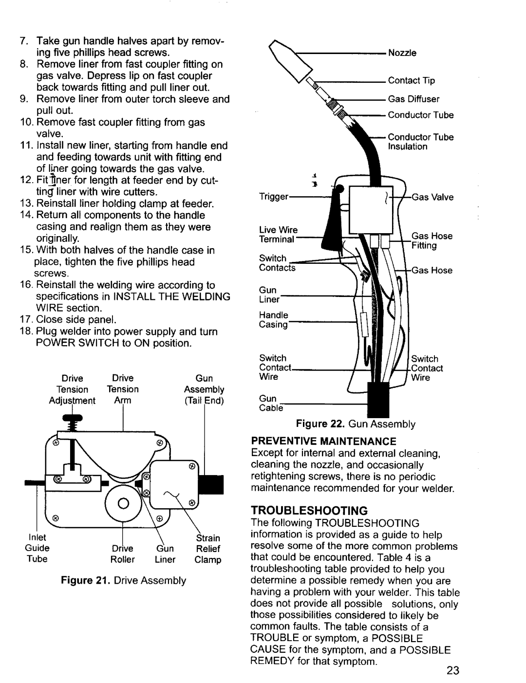
Nozzle
Contact Tip
Gas Diffuser
Conductor Tube
Jbe
Insulation
Trigg.
casing and realign them as they were |
originally. |
15. With both halves of the handle case in |
place, tighten the five phillips head screws.
16.Reinstall the welding wire according to specifications in INSTALL THE WELDING WIRE section.
17.Close side panel.
18.Plug welder into power supply and turn POWER SWITCH to ON position.
Live Wire
Switch Contacts
Gun
Liner
Handle
Casing
Gas Hose
Drive | Drive | Gun |
Tension | Tension | Assembly |
Adjustment | Arm | (Tail |
® |
|
|
|
Inlet |
|
| Strain |
Guide | Drive | Jn | Relief |
Tube | Roller | Liner | Clamp |
Figure | 21. Drive | Assembly |
|
SwitchSwitch
WireWire
Gun
Cable
Figure 22. Gun Assembly
PREVENTIVE MAINTENANCE
Except for internal and external cleaning,
cleaning the nozzle, and occasionally
retightening screws, there is no periodic maintenance recommended for your welder.
TROUBLESHOOTING
The following TROUBLESHOOTING information is provided as a guide to help resolve some of the more common problems that could be encountered. Table 4 is a troubleshooting table provided to help you determine a possible remedy when you are having a problem with your welder. This table does not provide all possible solutions, only those possibilities considered to likely be common faults. The table consists of a TROUBLE or symptom, a POSSIBLE CAUSE for the symptom, and a POSSIBLE REMEDY for that symptom.
23