shield handle. (DO NoT DISCARDT)
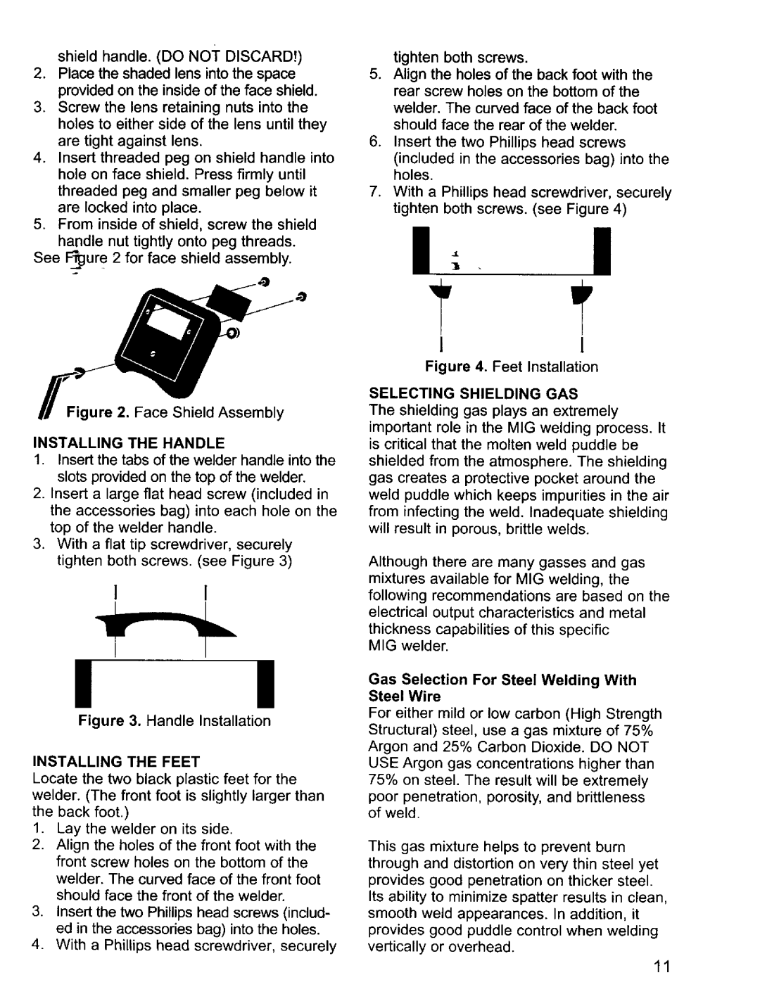
2.Place the shaded lens into the space provided on the inside of the face shield.
3.Screw the lens retaining nuts into the holes to either side of the lens until they are tight against lens.
4.Insert threaded peg on shield handle into hole on face shield. Press firmly until threaded peg and smaller peg below it are locked into place.
5.From inside of shield, screw the shield handle nut tightly onto peg threads.
See F_ur e 2 for face shield assembly.
Figure 2. Face Shield Assembly
INSTALLING THE HANDLE
1.Insert the tabs of the welder handle into the slots provided on the top of the welder.
2.Insert a large flat head screw (included in the accessories bag) into each hole on the top of the welder handle.
3.With a flat tip screwdriver, securely tighten both screws. (see Figure 3)
1 1
! I
Figure 3. Handle Installation
INSTALLING THE FEET
Locate the two black plastic feet for the welder. (The front foot is slightly larger than the back foot.)
1.Lay the welder on its side.
2.Align the holes of the front foot with the front screw holes on the bottom of the welder. The curved face of the front foot should face the front of the welder.
3.Insert the two Phillips head screws (includ- ed in the accessories bag) into the holes.
4.With a Phillips head screwdriver, securely
tighten both screws.
5.Align the holes of the back foot with the rear screw holes on the bottom of the welder. The curved face of the back foot should face the rear of the welder.
6.Insert the two Phillips head screws
(included in the accessories bag) into the holes.
7.With a Phillips head screwdriver, securely tighten both screws. (see Figure 4)
I- I
I1
Figure 4. Feet Installation
SELECTING SHIELDING GAS
The shielding gas plays an extremely
important role in the MIG welding process. It is critical that the molten weld puddle be shielded from the atmosphere. The shielding gas creates a protective pocket around the weld puddle which keeps impurities in the air from infecting the weld. Inadequate shielding will result in porous, brittle welds.
Although there are many gasses and gas mixtures available for MIG welding, the following recommendations are based on the electrical output characteristics and metal
thickness capabilities of this specific MIG welder.
Gas Selection For Steel Welding With
Steel Wire
For either mild or low carbon (High Strength Structural) steel, use a gas mixture of 75% Argon and 25% Carbon Dioxide. DO NOT USE Argon gas concentrations higher than 75% on steel. The result will be extremely
poor penetration, porosity, and brittleness of weld.
This gas mixture helps to prevent burn through and distortion on very thin steel yet provides good penetration on thicker steel. Its ability to minimize spatter results in clean, smooth weld appearances. In addition, it provides good puddle control when welding vertically or overhead.
11
