job. The VOLTAGE selector controls the weld heat. There are four voltage heat selections (lettered A through D) available on this welder. Position A provides the lowest voltage (heat) and position D the highest voltage (heat).
15.Set the WIRE SPEED control to the middle of the wire speed range.
16.Straighten the gun cable and pull the trigger on the welding gun to feed the wire through the gun assembly.
17.When at least an inch of wire sticks out pa,._tthe end of the gun, release the trigger.
18.Select a contact tip stamped with the same diameter as the wire being used. If stamped in metric see DESCRIPTION.
Note: Due to inherent variances in
19.Slide the contact tip over the wire (protruding from the end of the gun). Thread the contact tip into the end of the gun and
20.Install the nozzle on the gun assembly. For best results, coat the inside of the nozzle with
21.Cut off the excess wire that extends past the end of the nozzle.
SET THE WIRE DRIVE TENSION
To reduce the risk of arc flash, make certain that the wire coming out of the end of the gun does not come in contact with work piece, ground clamp or any grounded materi- al during the drive tension setting process or arcing will occur.
. Pull the trigger on the gun.
2.Turn the drive tension adjustment knob clockwise, increasing the drive tension until the wire seems to feed smoothly without slipping.
CHANGE POLARITY
This welder allows you the capability to change the welding current polarity. You may select either dc Straight (dc - Flux Cored) or dc Reverse Polarity (dc + MIG). For welding steel with solid wire, stainless steel, flux cored hardfacing of steel, and silicon bronze welding of steel, select dc Reverse Polarity (dc + MIG). When using
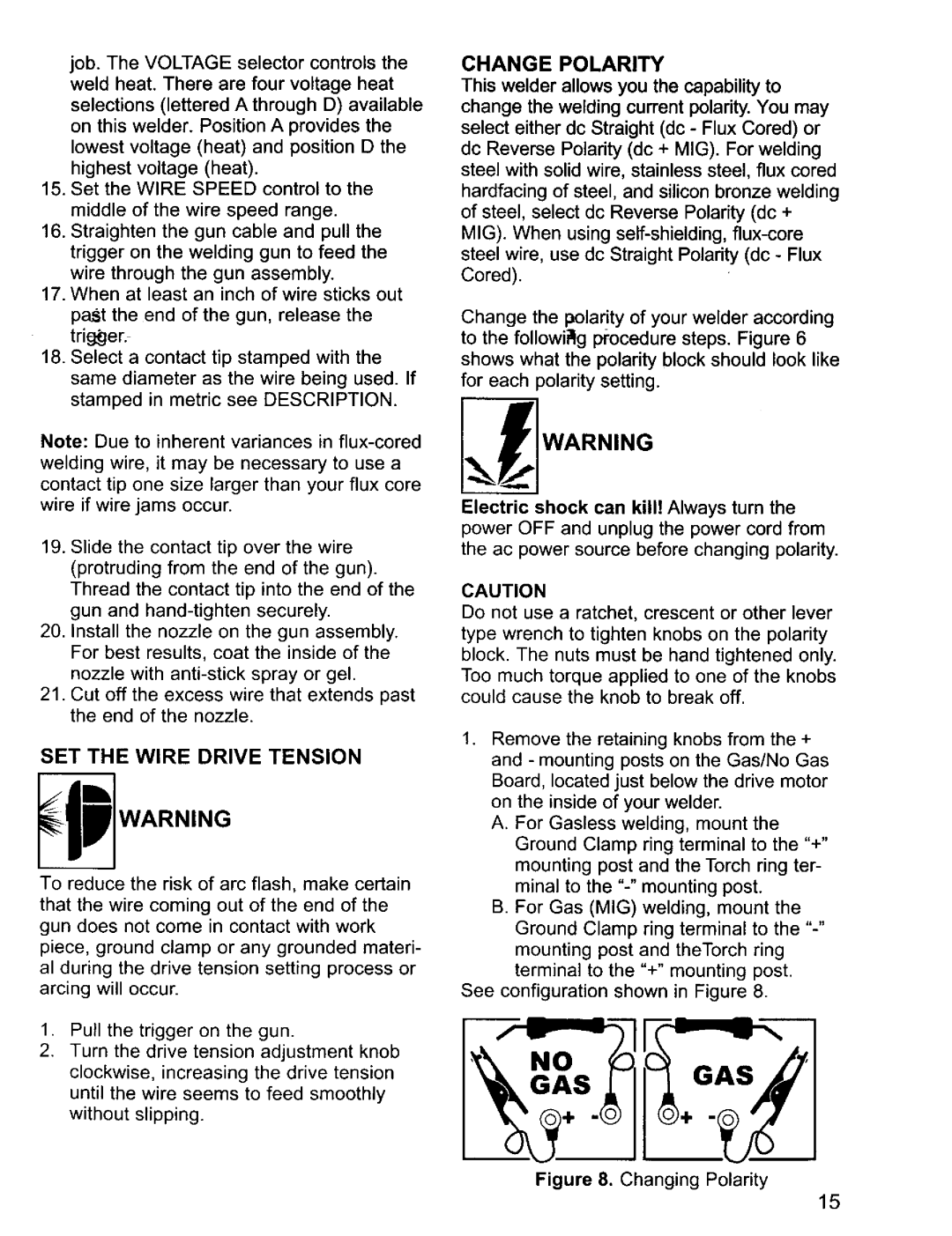
Change the polarity of your welder according to the followi_lg procedure steps. Figure 6 shows what the polarity block should look like for each polarity setting.
Electric shock can kill! Always turn the power OFF and unplug the power cord from the ac power source before changing polarity.
CAUTION
Do not use a ratchet, crescent or other lever type wrench to tighten knobs on the polarity block. The nuts must be hand tightened only. Too much torque applied to one of the knobs could cause the knob to break off.
1.Remove the retaining knobs from the + and - mounting posts on the Gas/No Gas Board, located just below the drive motor on the inside of your welder.
A.For Gasless welding, mount the Ground Clamp ring terminal to the "+" mounting post and the Torch ring ter- minal to the
B.For Gas (MIG) welding, mount the
Ground Clamp ring terminal to the
See configuration shown in Figure 8.
NO
GASGAS
Figure 8. Changing Polarity
15
