Fig. 8 | Fig. 9 | Fig. 10 |
Ribs on shaft
Grooves
Fig. 11
0 | 30 | 60 | 90 _ | 240' | 270' | 300' | 330' |
120150180'210
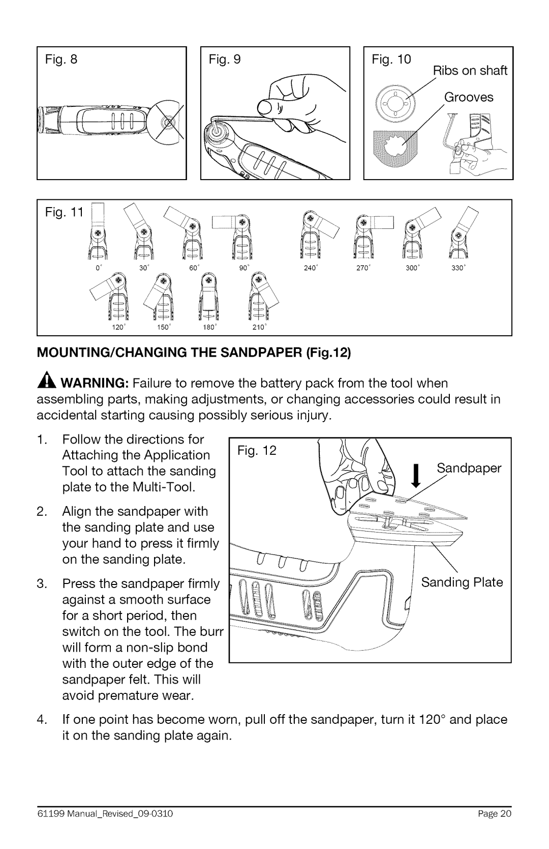
MOUNTING/CHANGING THE SANDPAPER (Fig.12)
A_, WARNING: Failure to remove the battery pack from the tool when assembling parts, making adjustments, or changing accessories could result in accidental starting causing possibly serious injury.
1.Follow the directions for
Attaching the Application Fig. 12 Tool to attach the sanding
plate to the
2.
3.
4.
Align the sandpaper with the sanding plate and use your hand to press it firmly on the sanding plate.
Press | the | sandpaper | firmly | Sanding Plate | |
against | a smooth | surface |
| ||
for a short period, then |
| ||||
switch on the tool. The burr |
| ||||
will form a |
| ||||
with the outer edge of the |
| ||||
sandpaper | felt. This | will |
| ||
avoid | premature | wear. |
| ||
If one point has become worn, pull off the sandpaper, turn it 120 ° and place it on the sanding plate again.
6±199 ManuaLRevised_09 | 0310 | Page 20 |
