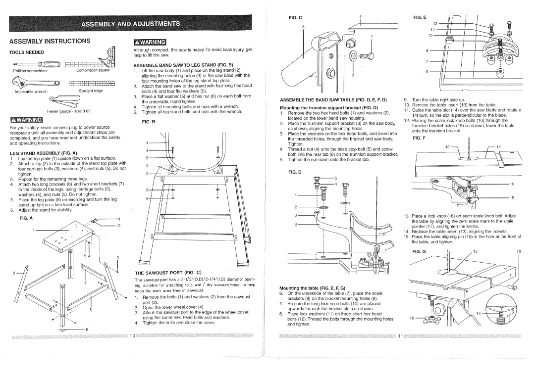
ASSEMBLY iNSTRUCTiONS
TOOLS NEEDED | . v(" |
_Ipl,l,l,l,_
Phillipsscrewdriver Combinationsquare
| _l_j41'l_l'l'('l | ' I'1' |
'Adjustable wrench | Straight edge |
|
_)
Feeler gauge - size 0.02
Although compact, this saw is heavy. To avoid back injury, get help to lift the saw.
ASSEMBLE BAND SAWTO LEG STAND (FIG. B)
1.Lift the saw body (1) and place on the leg stand (2), aligning the mounting holes (3) of the saw base with the four mounting holes of the leg stand top plate.
2.Attach the band saw to the stand with four long hex head bolts (4) and four flat washers (5).
3.Place a flat washer (5) and hex nut (6) on each bolt from the underside. Hand tighten.
4.Tighten all mounting bolts and nuts with a wrench.
5.Tighten all leg stand bolts and nuts with the wrench. FIG. B
FIG. C
3
ASSEMBLE THE BAND SAW TABLE (FIG. D, E, F, G)
Mounting the trunnion support bracket (FIG. D)
1. | Remove the two hex head bolts (1) and | washers (2), |
| located on the lower band saw housing. |
|
2. | Place the trunnion support bracket (3) on the saw body, | |
FIG. E |
12
1
9.Turn the table right side up.
10. | Remove | the table insert (13) from the table. | |
11. | Guide the table | slot (14) over the saw blade and rotate a | |
| 1/4 turn, so the | slot is perpendicular to the blade. | |
12. | Placing the scale lock knob bolts (10) through the | ||
| trunnion | bracket holes (15) as shown, lower the table | |
For your safety, never connect plug to power source receptacle until all assembly and adjustment steps are completed, and you have read and understood the safety and operating instructions.
LEG STAND ASSEMBLY (FIG. A)
1.Lay the top plate (1) upside down on a flat surface.
2.Attach a leg (2) to the outside of the stand top plate with four carriage bolts (3), washers (4), and nuts (5). Do not tighten.
3.Repeat for the remaining three legs.
4.Attach two long brackets (6) and two short brackets (7)
| to the | inside of the legs, using carriage | bolts (3), |
| 5 |
| |
| washers (4), and nuts (5). Do not tighten. | • | 6 | _ | |||
5. | Place | the leg pads (8) on each leg and turn the leg | |||||
|
|
| |||||
| stand | upright on a firm level surface. |
|
|
|
| |
6. | Adjust the stand for stability. |
|
|
|
| ||
| FIG. A | 11 |
|
|
| ||
|
| 1 |
|
|
|
| |
THE SAWDUST PORT (FIG. C)
| as shown, aligning | the mounting holes. |
3. | Place the washers | on the hex head bolts, and insert into |
| the threaded holes, through the bracket and saw body. | |
| Tighten. |
|
4. | Thread a nut (4) onto the table stop bolt (5) and screw | |
| both into the rear tab (6) on the trunnion support bracket. | |
5. | Tighten the nut down onto the bracket tab. | |
FIG. D
4•
1
2'9
i ,
3
onto the trunnion bracket. |
FIG. F
15
13.Place a lock knob (16) on each scale knob bolt. Adjust the table by aligning the zero scale mark to the scale pointer (17), and tighten the knobs.
14.Replace the table insert (13), aligning the indents.
15.Place the table aligning pin (18) in the hoie at the front of the table, and tighten.
FIG. G | 13 | 18 |
|
|
|
| i |
|
| The sawdust port has a |
| |
|
| ing, suitable for attaching to a wet / dry vacuum hose, to help |
| |
|
| keep the work area free of sawdust. |
| |
| , | '"',_ !. | Remove the bolts (1) and washers (2) from the sawdust | i |
|
|
| port (3). | i |
|
| 2. | Open the lower wheel cover (4). |
|
|
| 3. | Attach the sawdust port to the edge of the wheel cover, |
|
_, | .... |
| using the same hex. head bolts and washers. | :J |
| ...."_ | 4. | Tighten the bolts and close the cover. |
|
| 8 |
|
|
|
Mounting the table (FIG. E, F, G)
6.On the underside of the table (7), place the scale brackets (8) on the bracket mounting holes (9).
7.Be sure the long lock knob bolts (10) are placed upwards through the bracket slots as shown.
8.Place lock washers (11) on three short hex head
bolts (12). Thread the bolts through the mounting holes and tighten.
10