BLADE TENSION (FIG. M)
To avoid injury, turn the switch OFF and disconnect the saw from the power source before rnaking any adjustments, NEVER make tension adjustments with the machine running.
The gauge (1) on the bracket (2) at the rear of the upper wheel housing indicates the proper tension for the various blade widths.
1.Set the blade tension gauge to correspond with the width of the blade in use.
2.Turn the blade tension knob (3) clockwise, raising the upper wheel to tighten the blade. Turn the knob counterclockwise to lower the upper wheel, loosening the blade.
3.As you become familiar with the saw, you may want to change the tension settings.
NOTE: Changes in blade width and type of material
being cut will have an effect on the blade tension. Too much or too little tension could break the blade. When
the band saw is not in use, relax the blade tension.
F_G. M
If the blade moves toward the front of the wheel, turn the tracking knob (5) on the rear of the band saw clockwise.
This tilts the top of the wheel and moves the blade toward the center.
If the blade moves toward the back edge, turn the
tracking knob counterclockwise, moving the blade toward the center.
NO'rE: Turn the tracking knob SLIGHTLY to make blade tracking adjustments.
5
4
UPPER BLADE GUBDE ASSEMBLY (FIG. O)
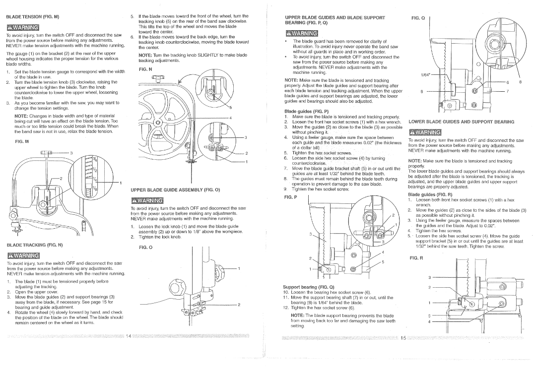
UPPER BLADE GUIDES AND BLADE SUPPORT BEARING (FIG. P, Q)
oThe blade guard has been removed for clarity of illustration. To avoid injury never operate the band saw without all guards in place and in working order.
To avoid injury, turn the switch OFF and disconnect the saw from the power source before making any adjustments. NEVER make adjustments with the machine running.
NOTE: Make sure the blade is tensioned and tracking properly. Adjust the blade guides and support bearing after each blade tension and Iracking adjustment. When the upper blade guides and supporl bearings are adjusted, the lower guides and bearings should also be adjusted.
Blade guides (HG. P)
!.Make sure the blade is tensioned and tracking properly.
2.Loosen the front hex socket screws (1) with a hex wrench.
3.Move the guides (2) as close to the blade (3) as possible without pinching it. :
4.Using a feeler gaugel make sure the space between
each guide and the blade measures 0.02!'(the thickness
of a dollar bill) ........
5.Tighten the hex socket screws:
6.Loosen the:side hex socket screw (4)by turning counterclockwise, ::
7.Move the blade guide: bracket shaft (5) in or out until the guide s are at least 1/3Z' behind the blade teeth.
8; The guides must remain behind the blade teeth during operation to prevent damage to the saw blade.
9.Tighten the hex socket screw. FIG. P
FIG. O
LOWER BLADE GUIDES AND SUPPORT BEARING
To avoid injury, turn the switch OFF and disconnect the saw from the power source before making any adjustments. NEVER make adjustments with the machine running.
NOTE: Make sure the blade is tensioned and tracking properly.
The lower blade guides and support bearings should always be adjusted after the blade is tensioned, the tracking is adjusted, and the upper blade guides and upper support bearings are properly adjusted.
Blade guides (FIG. R)
To avoid injury, turn the switch OFF and disconnect the saw from the power source before making any adjustments. NEVER make adjustments with the machine running.
1.Loosen the lock knob (1) and move the blade guide assembly (2) up or down to 1/8" above the workpiece.
2.Tighten the lock knob.
BLADE TRACKING (FIG, N) | FiG. O |
|
To avoid injury, turn the switch OFF and disconnect the saw from the power source before making any adjustments. NEVER make tension adjustments with the machine running.
1.The blade (1) must be tensioned properly before adjusting the tracking.
2.Open the upper cover.
3.Move the blade guides (2) and support bearings (3)
away from the blade, if necessary. See page 15 for | J |
bearing and guide adjustment. |
|
4.Rotate the wheel (4) slowly forward by hand, and check the position of the blade on the wheel. The blade should remain centered on the wheel as it turns.
.... | 0 ; 0: | ! | i;_ iO:i? | i: ¸:i; i ;£{i!:;:ill ;;ii _i!i¸iii!i¸¸I;I{i:i¸ii'i¸iii¸!iiiiiiii:;il14;: il;ii¸¸if:!!!ii:i!ii¸ii:;__};:iil¸ii!l¸¸ii;ii!!i¸:!!i¸¸ii!i!i:!iiil¸:il_iii!iii!i;il¸I!¸iilil¸ii!i!!!ii!iiiii!:!iiiSiiiiiIJi!iiii!iiiii!i!:iiiii!i!:!ili!iii:iii!!i!iiii!iii!iiii!:iii!!!iiiiiiiiiiiii!iliiii!i!iiii!i:ii:ii!i¸!ii'iiii:i¸i!!ii!ii:iiiiiiiii:i¸!!il¸¸!ii!i!!ii!!iii: !ili | ! |
4
2
5
1
Support bearing (FIG, Q)
10. Loosen the bearing hex socket screw (6).
11, Move the support bearing shaft (7:)in or out, until the bearing (8) is 1/64" behind the blade.
12.Tighten the hex socket screw (6).
NOTE: The blade support bearing prevents the blade from moving back too far and damaging the saw teeth setting.
1.Loosen both front hex socket screws (1) with a hex wrench.
2.Move the guides (2) as close to the sides of the blade (3) as possible without pinching it.
3.Using the feeler gauge, measure the spaces between the guides and the blade. Adjust to 0.02".
4.Tighten the hex screws.
5._ Loosen the side hex socket screw (4). Move the guide suppod bracket (5) in or out until the guides are at least 1/32" behind the saw teeth. Tighten the screw.
F_G, R
3
_'L_
2
I
iI