design cooling system. At the heart of this cooling system is an engineered fan. It is perfectly normal for this fan to blow air through the vent holes in large amounts. You know that the cooling system is working when air is being expelled.
Air Compressor Pump:
Compresses air into the air tank. Working air is not available until the compressor has raised the air tank pressure above that required at the air outlet.
Drain Valve: The drain valve is locat- ed at the base of the air tank and is used to drain condensation at the end of each use.
Check Valve: When the air compres- sor is operating, the check valve is
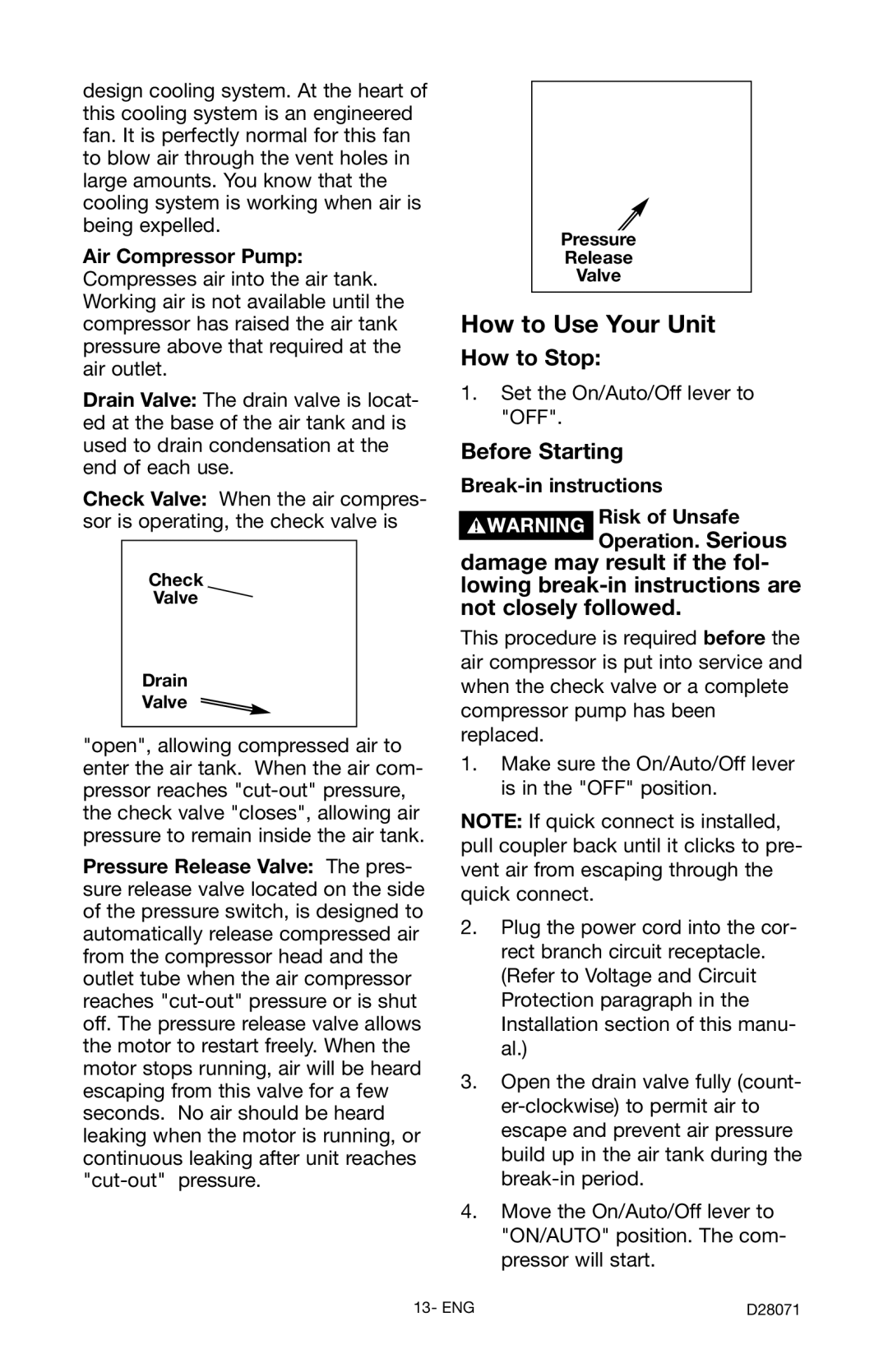
Check
Valve 
Drain
Valve![]()
"open", allowing compressed air to enter the air tank. When the air com- pressor reaches
Pressure Release Valve: The pres- sure release valve located on the side of the pressure switch, is designed to automatically release compressed air from the compressor head and the outlet tube when the air compressor reaches
Pressure
Release
Valve
How to Use Your Unit
How to Stop:
1.Set the On/Auto/Off lever to "OFF".
Before Starting
Break-in instructions
Risk of Unsafe
Operation. Serious
damage may result if the fol- lowing
This procedure is required before the air compressor is put into service and when the check valve or a complete compressor pump has been replaced.
1.Make sure the On/Auto/Off lever is in the "OFF" position.
NOTE: If quick connect is installed, pull coupler back until it clicks to pre- vent air from escaping through the quick connect.
2.Plug the power cord into the cor- rect branch circuit receptacle. (Refer to Voltage and Circuit Protection paragraph in the Installation section of this manu- al.)
3.Open the drain valve fully (count-
4.Move the On/Auto/Off lever to "ON/AUTO" position. The com- pressor will start.
13- ENG | D28071 |