JUMPER PLUG PROGRAMMING
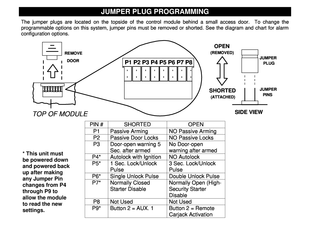
The jumper plugs are located on the topside of the control module behind a small access door. To change the programmable options on this system, jumper pins must be removed or shorted. See the diagram and chart for alarm configuration options.
REMOVE
DOOR
OPEN
(REMOVED)
P1 P2 P3 P4 P5 P6 P7 P8
JUMPER
PLUG
SHORTED
(ATTACHED)
JUMPER
PINS
TOP OF MODULE
SIDE VIEW
*This unit must be powered down and powered back up after making any Jumper Pin changes from P4 through P9 to allow the module to read the new settings.
PIN # | SHORTED | OPEN |
P1 | Passive Arming | NO Passive Arming |
P2 | Passive Door Locks | NO Passive Locks |
P3 | No | |
| Sec. after armed | warning after armed |
P4* | Autolock with Ignition | NO Autolock |
P5* | 1 Sec. Lock/Unlock | 3 Sec. Lock/Unlock |
| Pulse | Pulse |
P6* | Single Unlock Pulse | Double Unlock Pulse |
P7* | Normally Closed | Normally Open (High- |
| Starter Disable | Security Starter |
|
| Disable |
P8 | Not Used | Not Used |
P9* | Button 2 = AUX. 1 | Button 2 = Remote |
|
| Carjack Activation |
