WIRING: 9-PIN Connector Cont.
Blue/White:
This wire activates when the unlock button on the remote is pressed a second time within 15 seconds upon disarming. This wire is used for the Optional Separate Driver’s/Passenger Unlock feature. Connects to unlock circuit for passenger door or doors. See DOOR LOCK WIRING for special configuration options (pages
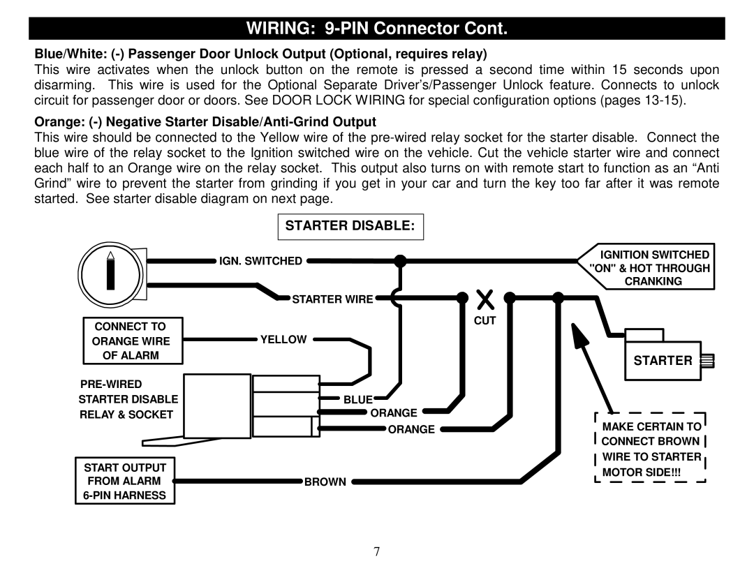
Orange: (-) Negative Starter Disable/Anti-Grind Output
This wire should be connected to the Yellow wire of the
STARTER DISABLE:
| IGN. SWITCHED | IGNITION SWITCHED | |
| "ON" & HOT THROUGH | ||
|
| ||
|
| CRANKING | |
| STARTER WIRE |
| |
CONNECT TO |
| CUT | |
YELLOW |
| ||
ORANGE WIRE |
| ||
OF ALARM |
| STARTER | |
|
| ||
|
| ||
STARTER DISABLE | BLUE |
| |
RELAY & SOCKET | ORANGE | MAKE CERTAIN TO | |
| ORANGE | ||
|
| CONNECT BROWN | |
START OUTPUT |
| WIRE TO STARTER | |
| MOTOR SIDE!!! | ||
FROM ALARM | BROWN | ||
| |||
|
|
7