CH and CL Series Power Amplifiers
2Setup
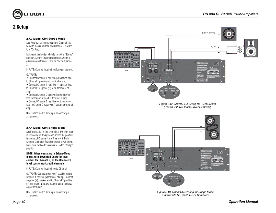
2.7.3Model CH4 Stereo Mode
See Figure 2.12. In this example, Channel 1 is wired to a 4/8 ohm load and Channel 2 is wired to a 70V load.
Make sure the Mode switch is set to the “Stereo” position. Set the Channel Operation Switch to 4/8 ohms on Channel1, and to 70V on Channel 2.
INPUTS: Connect input wiring for each channel.
OUTPUTS:
•Connect Channel 1 positive (+) speaker lead to Channel 1 positive (+) terminal of amp.
•Connect Channel 1 negative
•Connect Channel 2 positive (+) transformer lead to Channel 2 positive terminal of amp.
•Connect Channel 2 negative
Refer to Section 2.5 for output connector pin assignments.
2.7.4 Model CH4 Bridge Mode
See Figure 2.13. In this example, a
NOTE: When operating in
INPUTS: Connect input wiring to Channel 1.
OUTPUTS: Connect positive (+) speaker lead to Channel 1 positive (+) terminal of amp. Connect negative
(+)terminal of amp. Do not connect to negative output terminals.
Refer to Section 2.5 for output connector pin assignments.
8 or 4 ohms
70 V
Figure 2.12 Model CH4 Wiring for Stereo Mode
(Shown with No-Touch Cover Removed)
+ |
Mixer
Figure 2.13 Model CH4 Wiring for Bridge Mode
(Shown with No-Touch Cover Removed)
page 10 | Operation Manual |
