Crown Audio CH Series Principles of Operation, CH and CL Series Power Amplifiers, page

Models: CL Series CH Series

1 44
Download 44 pages 28.33 Kb
Page 25
Image 25
5.2 CH4 and CL4

CH and CL Series Power Amplifiers

5 Principles of Operation

5.2 CH4 and CL4

5.2.1 Audio Signal Path

For the sake of simplicity, only channel one of the audio signal path is described.

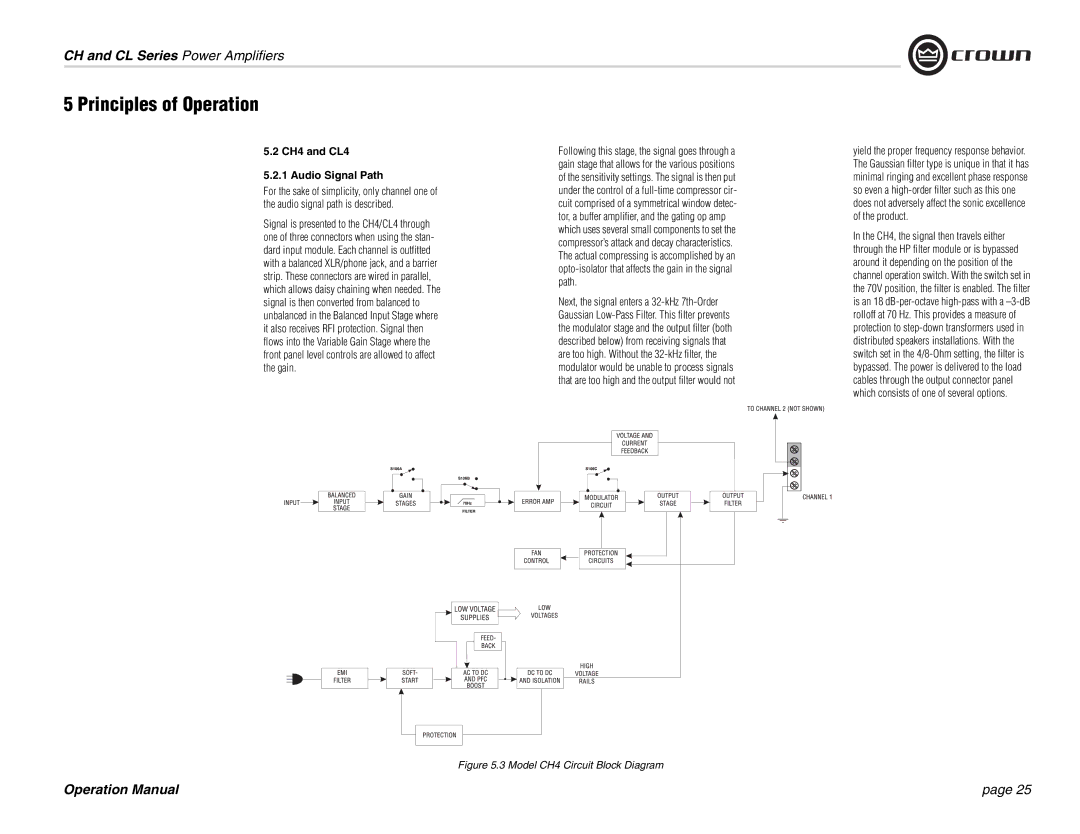
Signal is presented to the CH4/CL4 through one of three connectors when using the stan- dard input module. Each channel is outfitted with a balanced XLR/phone jack, and a barrier strip. These connectors are wired in parallel, which allows daisy chaining when needed. The signal is then converted from balanced to unbalanced in the Balanced Input Stage where it also receives RFI protection. Signal then flows into the Variable Gain Stage where the front panel level controls are allowed to affect the gain.

Following this stage, the signal goes through a gain stage that allows for the various positions of the sensitivity settings. The signal is then put under the control of a full-time compressor cir- cuit comprised of a symmetrical window detec- tor, a buffer amplifier, and the gating op amp which uses several small components to set the compressor’s attack and decay characteristics. The actual compressing is accomplished by an opto-isolator that affects the gain in the signal path.

Next, the signal enters a 32-kHz 7th-Order Gaussian Low-Pass Filter. This filter prevents the modulator stage and the output filter (both described below) from receiving signals that are too high. Without the 32-kHz filter, the modulator would be unable to process signals that are too high and the output filter would not

yield the proper frequency response behavior. The Gaussian filter type is unique in that it has minimal ringing and excellent phase response so even a high-order filter such as this one does not adversely affect the sonic excellence of the product.

In the CH4, the signal then travels either through the HP filter module or is bypassed around it depending on the position of the channel operation switch. With the switch set in the 70V position, the filter is enabled. The filter is an 18 dB-per-octave high-pass with a –3-dB rolloff at 70 Hz. This provides a measure of protection to step-down transformers used in distributed speakers installations. With the switch set in the 4/8-Ohm setting, the filter is bypassed. The power is delivered to the load cables through the output connector panel which consists of one of several options.

Figure 5.3 Model CH4 Circuit Block Diagram

Operation Manual

page 25

Page 25
Image 25
Crown Audio Principles of Operation, CH and CL Series Power Amplifiers, page, 5.2 CH4 and CL4 5.2.1 Audio Signal Path