CH and CL Series Power Amplifiers
5 Principles of Operation
5.1 CH1, CH2, CL1 and CL2
For the sake of simplicity, only channel one of the amplifier is described.
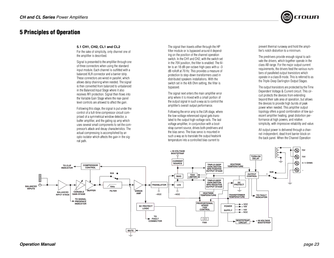
Signal is presented to the amplifier through one of three connectors when using the standard input module. Each channel is outfitted with a balanced XLR connector and a barrier strip. These connectors are wired in parallel, which allows daisy chaining when needed. The signal is then converted from balanced to unbalanced in the Balanced Input Stage where it also receives RFI protection. Signal then flows into the Variable Gain Stage where the
Following this stage, the signal is put under the control of a
BALANCED
INPUT STAGE
The signal then travels either through the HP filter module or is bypassed around it depend- ing on the position of the channel operation switch. In the CH1 and CH2, with the switch set in the 70V position, the filter is enabled. The fil- ter is an 18
The signal next enters the main amplifier error amp where it is mixed with a small portion of the output signal in such a way as to control the amplifier’s overall output performance.
Following the error amp is the LVA stage, where the
prevent thermal runaway and hold the ampli- fier’s notch distortion to a minimum.
The predrivers provide enough signal to acti- vate the drivers, which together operate in the class AB range. For the major output current requirements, the drivers feed the various num- bers of paralleled output transistors which operate in a class B mode. This is referred to as the
The output transistors are protected by the Time Dependent Voltage & Current circuit. This cir- cuit protects the devices from extending beyond their safe area of operation, but allows the devices to provide high bursts of peak power when needed. This amplifier output topology offers a good combination of low qui- escent amplifier heating, great distortion per- formance at high powers, and relative simplicity, with impressive reliability and value.
All output power is delivered through a chan-
70V
70V
4 / 8 OHMS
–
 Figure 5.1 Models CH1 & CH2 Circuit Block Diagram
Operation Manual | page 23 |