CH and CL Series Power Amplifiers
3 Operation
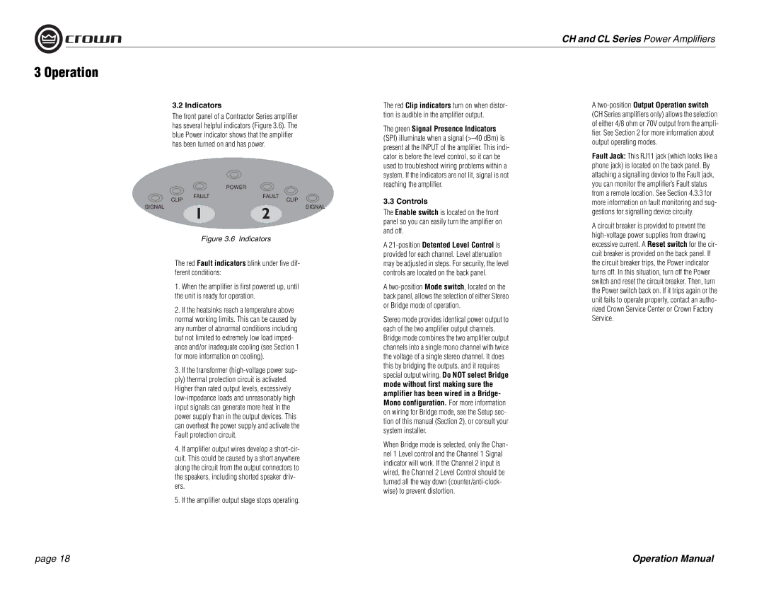
3.2 Indicators
The front panel of a Contractor Series amplifier has several helpful indicators (Figure 3.6). The blue Power indicator shows that the amplifier has been turned on and has power.
|
| POWER |
|
CLIP | FAULT | FAULT | CLIP |
|
| ||
SIGNAL |
|
| SIGNAL |
Figure 3.6 Indicators
The red Fault indicators blink under five dif- ferent conditions:
1. When the amplifier is first powered up, until the unit is ready for operation.
2. If the heatsinks reach a temperature above normal working limits. This can be caused by any number of abnormal conditions including but not limited to extremely low load imped- ance and/or inadequate cooling (see Section 1 for more information on cooling).
3. If the transformer
4. If amplifier output wires develop a
5. If the amplifier output stage stops operating.
The red Clip indicators turn on when distor- tion is audible in the amplifier output.
The green Signal Presence Indicators (SPI) illuminate when a signal
3.3 Controls
The Enable switch is located on the front panel so you can easily turn the amplifier on and off.
A
A
Stereo mode provides identical power output to each of the two amplifier output channels. Bridge mode combines the two amplifier output channels into a single mono channel with twice the voltage of a single stereo channel. It does this by bridging the outputs, and it requires special output wiring. Do NOT select Bridge mode without first making sure the amplifier has been wired in a Bridge- Mono configuration. For more information on wiring for Bridge mode, see the Setup sec- tion of this manual (Section 2), or consult your system installer.
When Bridge mode is selected, only the Chan- nel 1 Level control and the Channel 1 Signal indicator will work. If the Channel 2 input is wired, the Channel 2 Level Control should be turned all the way down
A
Fault Jack: This RJ11 jack (which looks like a phone jack) is located on the back panel. By attaching a signalling device to the Fault jack, you can monitor the amplifier’s Fault status from a remote location. See Section 4.3.3 for more information on fault monitoring and sug- gestions for signalling device circuity.
A circuit breaker is provided to prevent the
page 18 | Operation Manual |