CH and CL Series Power Amplifiers
2 Setup
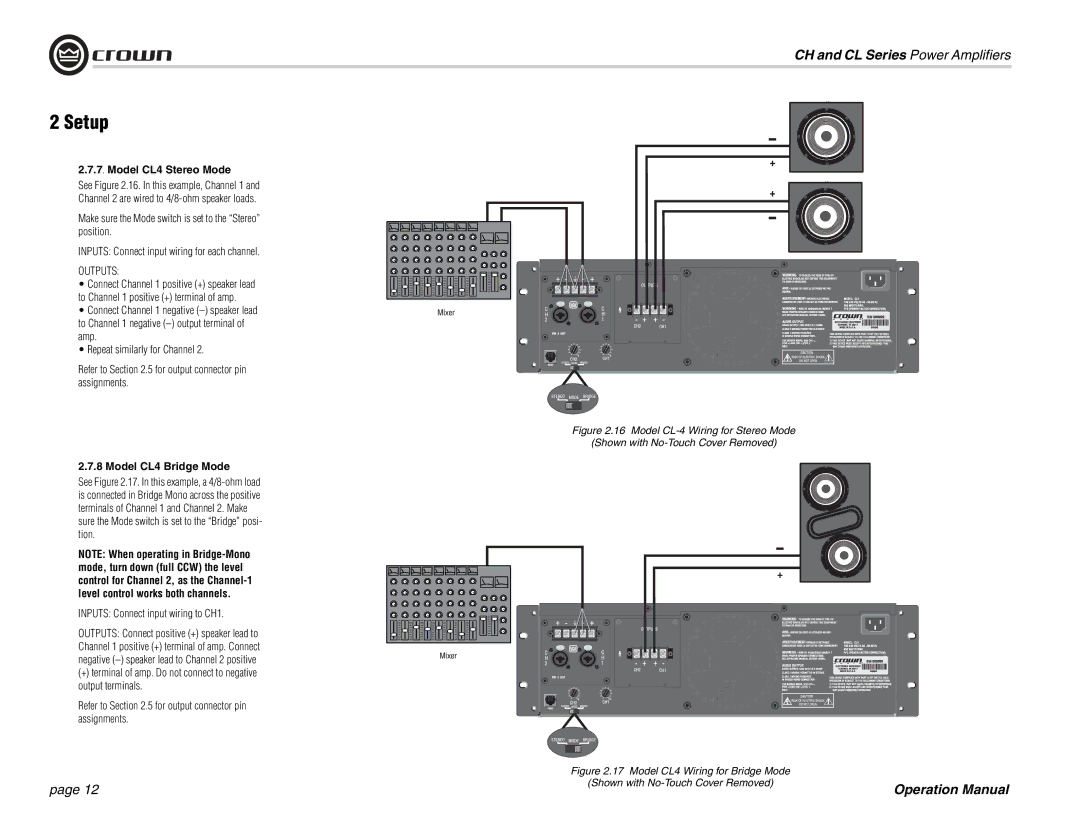
2.7.7. Model CL4 Stereo Mode
See Figure 2.16. In this example, Channel 1 and
Channel 2 are wired to
Make sure the Mode switch is set to the “Stereo” position.
INPUTS: Connect input wiring for each channel.
OUTPUTS:
• Connect Channel 1 positive (+) speaker lead to Channel 1 positive (+) terminal of amp.
• Connect Channel 1 negative
• Repeat similarly for Channel 2.
Refer to Section 2.5 for output connector pin assignments.
Figure 2.16 Model CL-4 Wiring for Stereo Mode
(Shown with No-Touch Cover Removed)
2.7.8 Model CL4 Bridge Mode
See Figure 2.17. In this example, a
NOTE: When operating in
INPUTS: Connect input wiring to CH1.
OUTPUTS: Connect positive (+) speaker lead to Channel 1 positive (+) terminal of amp. Connect negative
(+) terminal of amp. Do not connect to negative output terminals.
Refer to Section 2.5 for output connector pin assignments.
Figure 2.17 Model CL4 Wiring for Bridge Mode
page 12
(Shown with No-Touch Cover Removed)
Operation Manual
