
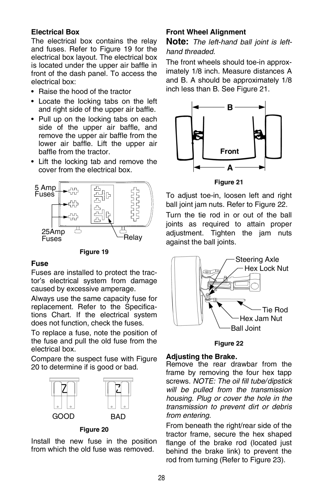
GT 3200 specifications
The Cub Cadet GT 3200 is a powerful garden tractor that combines robust performance with innovative technology, making it ideal for homeowners and landscapers alike. This formidable machine is equipped with a heavy-duty Kohler engine, offering a variety of horsepower options to meet diverse needs. Whether used for mowing large lawns or tackling tough garden tasks, the GT 3200 proves to be a reliable workhorse.One of the highlights of the GT 3200 is its Hydrostatic transmission, which provides seamless speed control without the need for manual gear shifting. This feature allows operators to easily navigate varying terrains, ensuring smooth operation in both forward and reverse. The precision steering system enhances maneuverability, making it easier to negotiate tight spaces and garden beds.
The GT 3200 boasts a cutting deck available in various sizes, including 48-inch and 54-inch options. This adaptability enables users to choose the size that best fits their mowing requirements. The deck is designed for efficiency, with dual-blade construction that delivers a clean, even cut across different grass types and terrain. Additionally, the deck’s adjustable cutting height allows for customized results, catering to users' specific aesthetic preferences.
Another notable characteristic of the Cub Cadet GT 3200 is its modular design, which allows for easy attachment of various implements. This versatility makes the GT 3200 suitable for multiple tasks, from mowing to snow clearing or tilling, as it can be equipped with a range of attachments such as snow blowers, front blades, and garden tillers.
Cub Cadet has integrated advanced technology in the GT 3200, including a digital gauge cluster that provides vital information at a glance, such as fuel levels and engine performance metrics. This technology enhances user experience and helps operators maintain optimal performance.
In terms of comfort, the GT 3200 comes with an ergonomic seat and intuitive controls, ensuring that operators can work for extended periods without discomfort. The high-back seat provides excellent support, and the easy-to-reach controls simplify operation, making mowing and gardening tasks less strenuous.
In summary, the Cub Cadet GT 3200 is a versatile, powerful, and technologically advanced garden tractor that offers a wide range of features designed to enhance performance and user experience. Whether for comprehensive lawn care or diverse landscaping tasks, the GT 3200 stands out as a top choice for those seeking quality and reliability in outdoor equipment.