BASE UNIT Controls
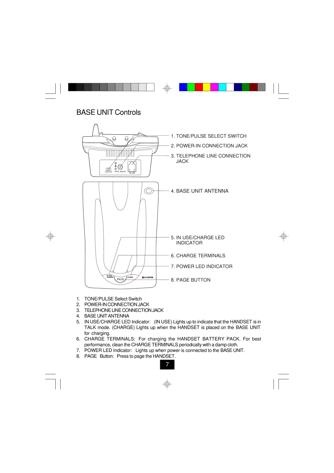
1. TONE/PULSE SELECT SWITCH
2.
3. TELEPHONE LINE CONNECTION JACK
PAGE
 4. BASE UNIT ANTENNA
5.IN USE/CHARGE LED INDICATOR
6.CHARGE TERMINALS
7.POWER LED INDICATOR
8.PAGE BUTTON
1.TONE/PULSE Select Switch
2.
3.TELEPHONE LINE CONNECTION JACK
4.BASE UNIT ANTENNA
5.IN USE/CHARGE LED Indicator: (IN USE) Lights up to indicate that the HANDSET is in TALK mode. (CHARGE) Lights up when the HANDSET is placed on the BASE UNIT for charging.
6.CHARGE TERMINALS: For charging the HANDSET BATTERY PACK. For best performance, clean the CHARGE TERMINALS periodically with a damp cloth.
7.POWER LED Indicator: Lights up when power is connected to the BASE UNIT.
8.PAGE Button: Press to page the HANDSET.
7