CY25566
Modulation Rate
Spread Spectrum clock generators utilize frequency modulation (FM) to distribute energy over a specific band of frequencies. The maximum frequency of the clock (Fmax) and minimum frequency of the clock (Fmin) determine this band of frequencies. The time required to transition from Fmin to Fmax and back to Fmin is the period of the Modulation Rate, Tmod. Modulation Rates of SSCG clocks are generally referred to in terms of frequency or Fmod = 1/Tmod.
The input clock frequency, Fin, and the internal divider count, Cdiv, determine the Modulation Rate. The CY25566 utilizes two different modulation rate dividers, depending on the range selected on S2 and S3 digital control inputs. Refer to the example below.
S3, S2 | CDiv | Output Frequency |
0,0 | 1166 | 1X |
|
|
|
0,1 | 1166 | 2X |
|
|
|
1,0 | 2332 | 1X |
|
|
|
1,1 | N/A | N/A |
|
|
|
Example:
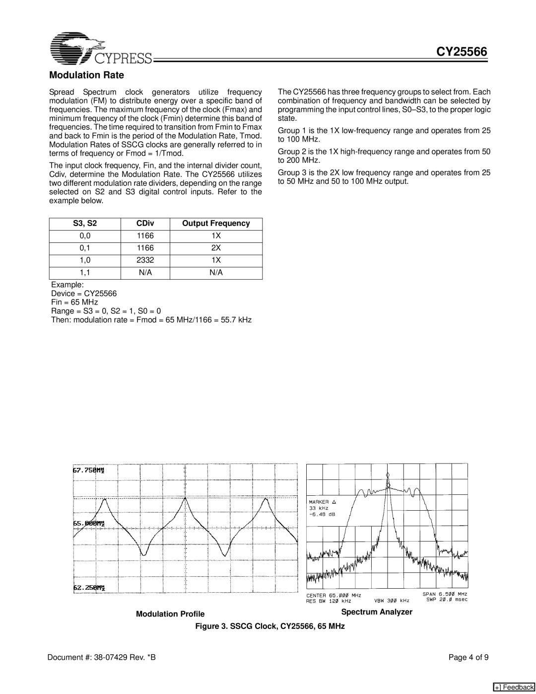
Device = CY25566 Fin = 65 MHz
Range = S3 = 0, S2 = 1, S0 = 0
Then: modulation rate = Fmod = 65 MHz/1166 = 55.7 kHz
The CY25566 has three frequency groups to select from. Each combination of frequency and bandwidth can be selected by programming the input control lines,
Group 1 is the 1X
Group 2 is the 1X
Group 3 is the 2X low frequency range and operates from 25 to 50 MHz and 50 to 100 MHz output.
Modulation Profile | Spectrum Analyzer |
Figure 3. SSCG Clock, CY25566, 65 MHz | |
Document #: | Page 4 of 9 |
[+] Feedback