
CY62148EV30 specifications
Cypress CY62148EV30 is a high-performance static random-access memory (SRAM) module renowned for its speed, low power consumption, and versatile applications in various electronic systems. With a storage capacity of 2 megabits (256K x 8 bits), this SRAM is ideal for developers seeking reliable memory solutions for high-speed computing tasks.One of the standout features of the CY62148EV30 is its fast access time, which can be as low as 30 nanoseconds, allowing for rapid data retrieval and storage. This makes it particularly well-suited for applications that require quick response times, such as embedded systems, telecommunications, and automotive electronics.
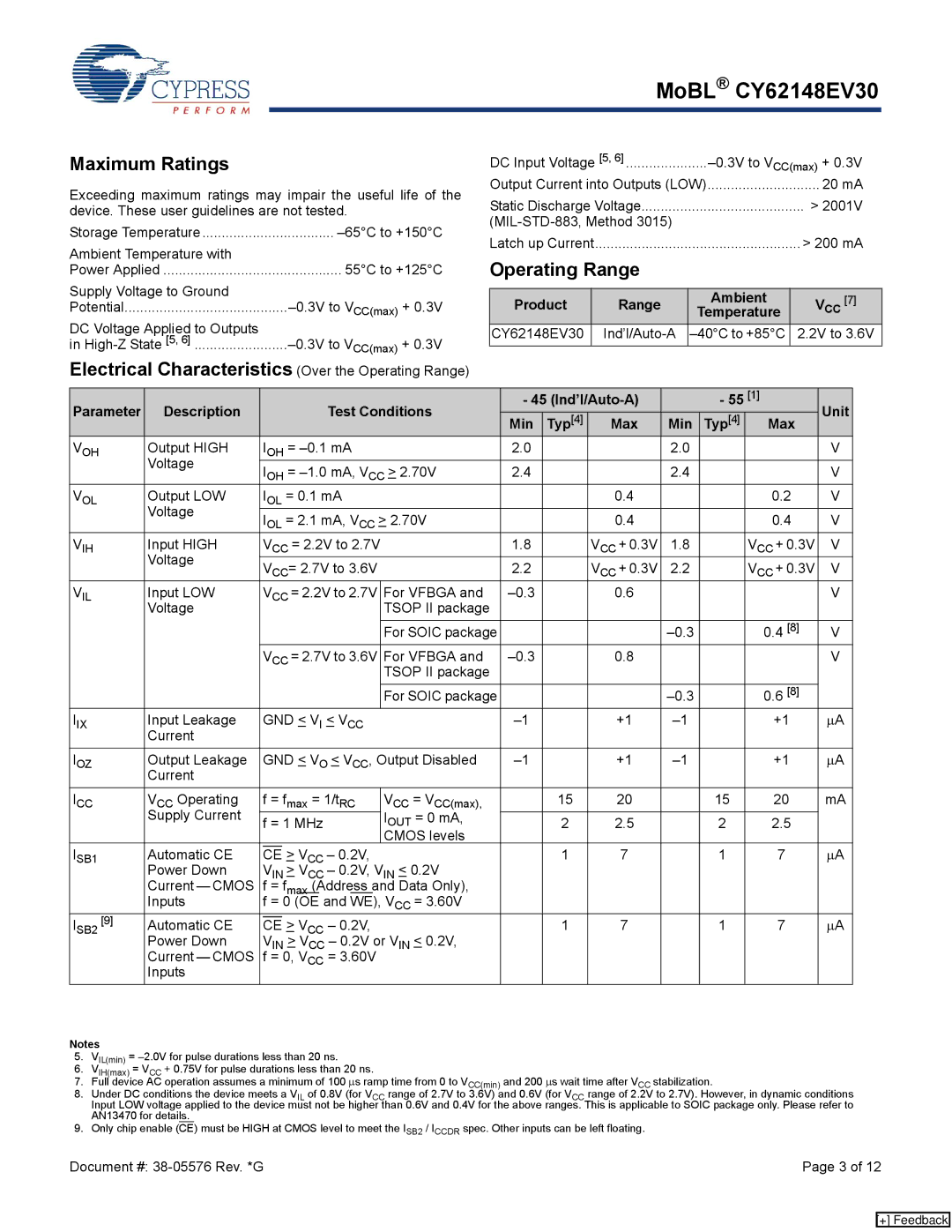
The CY62148EV30 is built using advanced CMOS technology, resulting in a low standby current that significantly prolongs battery life in portable devices. This characteristic is crucial for mobile applications where power efficiency is paramount. The SRAM operates on a wide voltage range, typically between 2.7V and 3.6V, accommodating various system designs and enhancing compatibility with different voltage levels prevalent in modern electronics.
The device features a simple asynchronous interface with straightforward read and write operations. Its dual-port capability enables simultaneous access by multiple devices, enhancing performance in multi-processor or multi-user environments. This is particularly beneficial in networking applications where high-speed data exchange is essential.
Furthermore, the CY62148EV30 is designed with high reliability in mind. It includes built-in features such as data retention voltage, which ensures that data is preserved even in low power scenarios. Additionally, the device supports a wide temperature range, making it capable of functioning effectively in diverse environmental conditions.
The versatility of the CY62148EV30 extends to various applications, including cache memory for microcontrollers, buffers in communication systems, and data storage in digital signal processing environments. Its robust characteristics and performance capabilities make it a preferred choice for engineers seeking a high-quality, reliable SRAM solution.
In summary, the Cypress CY62148EV30 is an exemplary SRAM offering that combines high speed, low power consumption, and versatile application compatibility. With its advanced technology, fast access times, low standby current, and reliability features, it stands out as a key component in a myriad of modern electronic systems.