CY7C1019CV33
Package Diagrams (continued)
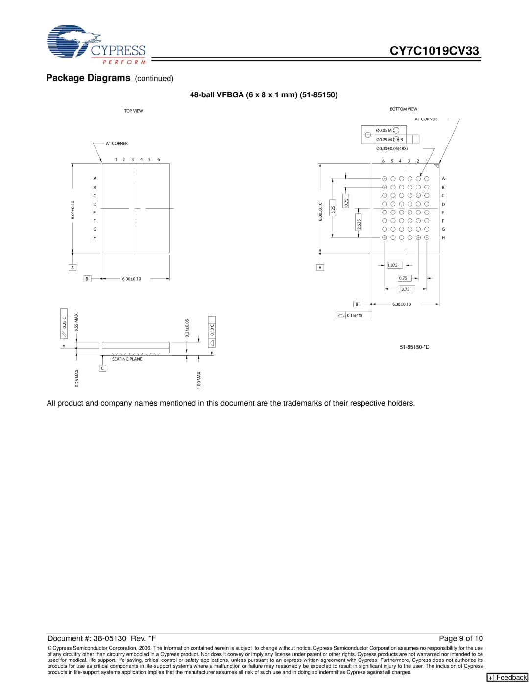
48-ball VFBGA (6 x 8 x 1 mm) (51-85150)
8.00±0.10
TOP VIEW
A1 CORNER
1 2 3 4 5 6
A
B
C
D
E
F
G
H
8.00±0.10
5.25
0.75
2.625
BOTTOM VIEW
A1 CORNER
Ø0.05 M C Ø0.25 M C A B Ø0.30±0.05(48X)
6 5 4 3 2 1
A
B
C
D
E
F
G
H
A
B
0.25 C | 0.55 MAX. |
0.26 MAX.
6.00±0.10
0.21±0.05 | 0.10 C |
SEATING PLANE |
|
C | 1.00 MAX |
|
A
B
0.15(4X)
1.875
0.75
3.75
6.00±0.10
All product and company names mentioned in this document are the trademarks of their respective holders.
Document #: | Page 9 of 10 |
© Cypress Semiconductor Corporation, 2006. The information contained herein is subject to change without notice. Cypress Semiconductor Corporation assumes no responsibility for the use of any circuitry other than circuitry embodied in a Cypress product. Nor does it convey or imply any license under patent or other rights. Cypress products are not warranted nor intended to be used for medical, life support, life saving, critical control or safety applications, unless pursuant to an express written agreement with Cypress. Furthermore, Cypress does not authorize its products for use as critical components in
[+] Feedback