|
| PRELIMINARY |
|
| CY7C1333H |
| ||
|
|
|
|
|
|
|
|
|
Switching Characteristics Over the Operating Range (continued)[12, 13] |
|
|
|
|
|
| ||
|
|
| 133 MHz | 100 MHz |
|
| ||
Parameter |
| Description | Min. | Max. | Min. | Max. | Unit |
|
Hold Times |
|
|
|
|
|
|
|
|
tAH
tALH
tWEH
tCENH
tDH
tCEH
Address Hold after CLK Rise | 0.5 |
| 0.5 |
| ||||||
|
|
|
|
|
| Hold after CLK Rise | 0.5 |
| 0.5 |
|
ADV/LD |
|
|
| |||||||
|
|
|
| [A:D] Hold after CLK Rise | 0.5 |
| 0.5 |
| ||
WE, | BW | |||||||||
CEN | Hold after CLK Rise | 0.5 |
| 0.5 |
| |||||
Data Input Hold after CLK Rise | 0.5 |
| 0.5 |
| ||||||
Chip Enable Hold after CLK Rise | 0.5 |
| 0.5 |
| ||||||
|
|
|
|
|
|
|
|
|
|
|
ns
ns
ns
ns
ns
ns
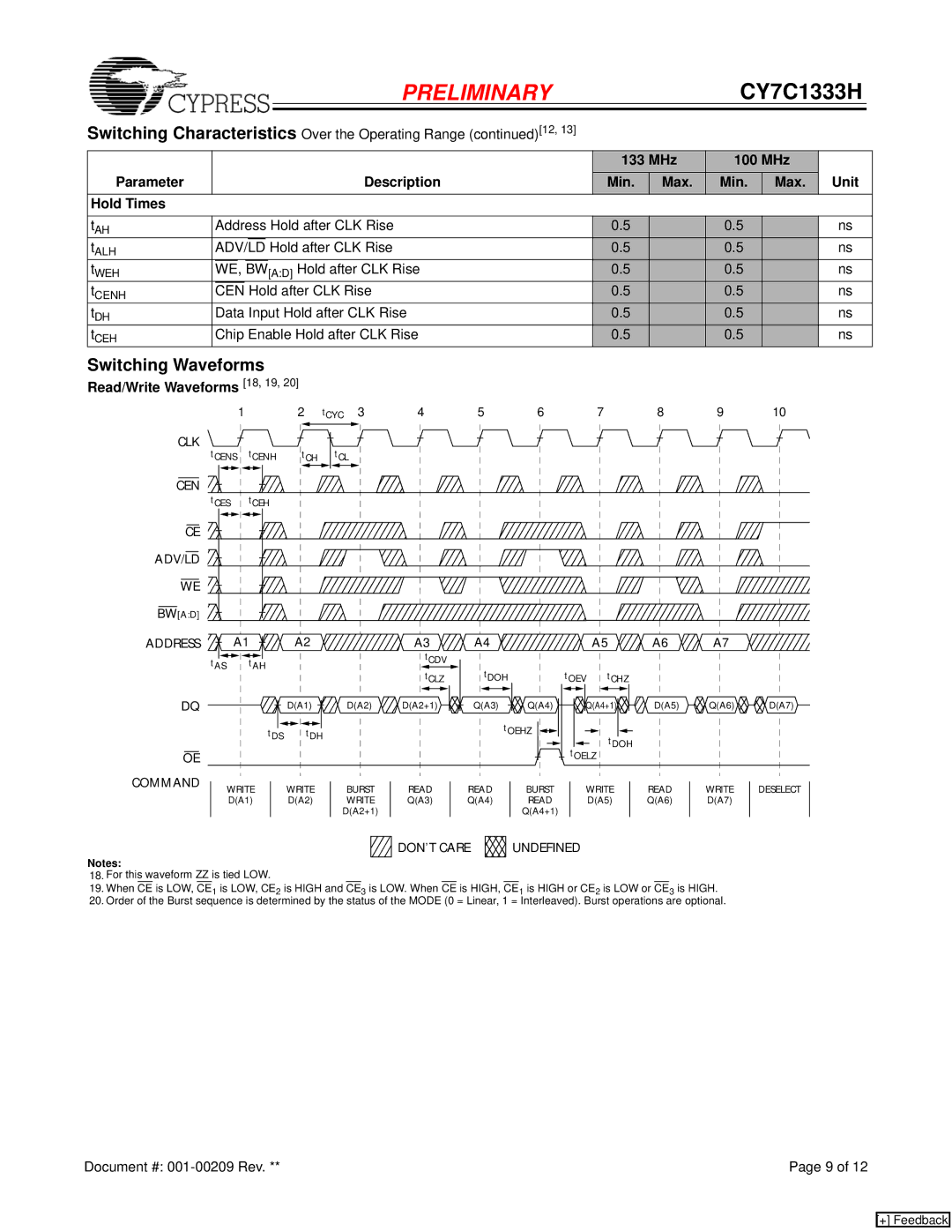
Switching Waveforms
Read/Write Waveforms [18, 19, 20]
|
| 1 | 2 | tCYC 3 | 4 | 5 | 6 | 7 | 8 | 9 | 10 |
CLK | tCENS | tCENH | tCH | tCL |
|
|
|
|
|
|
|
|
|
|
|
|
|
|
| ||||
CEN |
|
|
|
|
|
|
|
|
|
|
|
| tCES | tCEH |
|
|
|
|
|
|
|
|
|
CE |
|
|
|
|
|
|
|
|
|
|
|
ADV/LD |
|
|
|
|
|
|
|
|
|
|
|
WE |
|
|
|
|
|
|
|
|
|
|
|
BW[A:D] |
|
|
|
|
|
|
|
|
|
|
|
ADDRESS | A1 | A2 |
| A3 | A4 |
| A5 | A6 | A7 |
| |
| tAS | tAH |
|
| tCDV |
|
|
|
|
|
|
|
|
| tCLZ | tDOH |
| tOEV tCHZ |
|
|
| ||
|
|
|
|
|
|
|
|
| |||
DQ |
|
| D(A1) | D(A2) | D(A2+1) | Q(A3) | Q(A4) | Q(A4+1) | D(A5) | Q(A6) | D(A7) |
|
| tDS | tDH |
| tOEHZ | tDOH |
|
|
| ||
OE |
|
|
|
|
|
|
| tOELZ |
|
|
|
COMMAND | WRITE | WRITE | BURST | READ | READ | BURST | WRITE | READ | WRITE | DESELECT | |
| |||||||||||
| D(A1) | D(A2) | WRITE | Q(A3) | Q(A4) | READ | D(A5) | Q(A6) | D(A7) |
| |
|
|
|
| D(A2+1) |
|
| Q(A4+1) |
|
|
|
|
|
|
|
|
| DON’T CARE | UNDEFINED |
|
|
| ||
Notes:
18.For this waveform ZZ is tied LOW.
19.When CE is LOW, CE1 is LOW, CE2 is HIGH and CE3 is LOW. When CE is HIGH, CE1 is HIGH or CE2 is LOW or CE3 is HIGH.
20.Order of the Burst sequence is determined by the status of the MODE (0 = Linear, 1 = Interleaved). Burst operations are optional.
Document #: | Page 9 of 12 |
[+] Feedback