Rear Panel
AC Power Connector
Figure 5 – Rear panel of the Switch
AC Power Connector:
Plug in the female connector of the provided power cord into this connector, and the male into a power outlet. Supported input voltages range from
Understanding LED Indicators
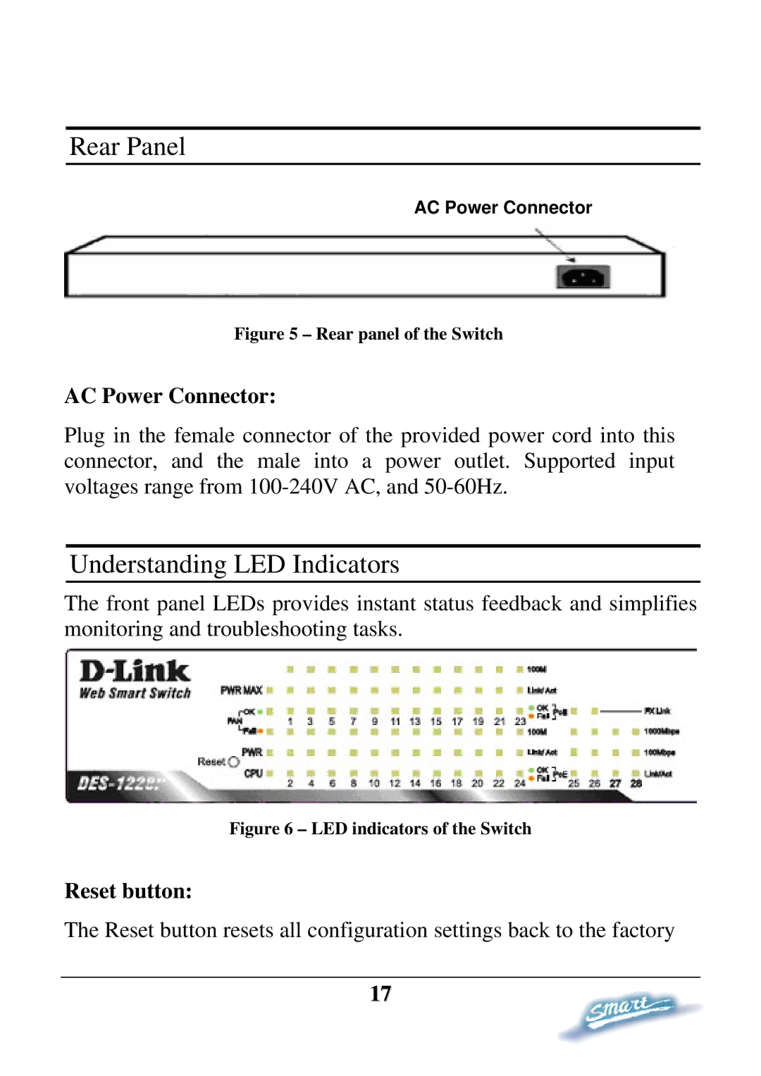
The front panel LEDs provides instant status feedback and simplifies monitoring and troubleshooting tasks.
Figure 6 – LED indicators of the Switch
Reset button:
The Reset button resets all configuration settings back to the factory
17