No | Name | Description |
| |
|
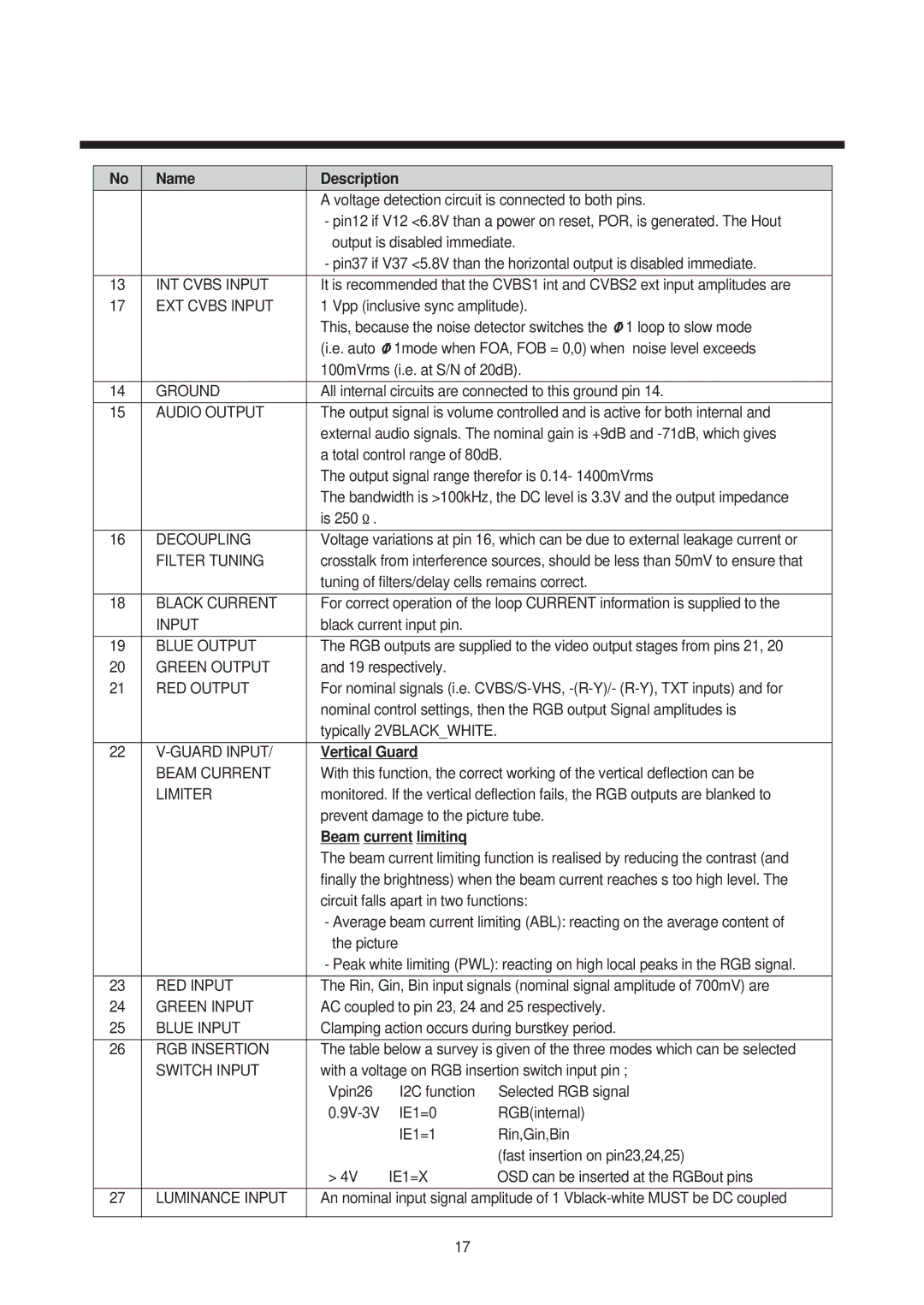
| A voltage detection circuit is connected to both pins. | ||
|
| - pin12 if V12 <6.8V than a power on reset, POR, is generated. The Hout | ||
|
| output is disabled immediate. | ||
|
| - pin37 if V37 <5.8V than the horizontal output is disabled immediate. | ||
|
|
| ||
13 | INT CVBS INPUT | It is recommended that the CVBS1 int and CVBS2 ext input amplitudes are | ||
17 | EXT CVBS INPUT | 1 Vpp (inclusive sync amplitude). | ||
|
| This, because the noise detector switches the 1 loop to slow mode | ||
|
| (i.e. auto | 1mode when FOA, FOB = 0,0) when noise level exceeds | |
|
| 100mVrms (i.e. at S/N of 20dB). | ||
|
|
| ||
14 | GROUND | All internal circuits are connected to this ground pin 14. | ||
|
|
| ||
15 | AUDIO OUTPUT | The output signal is volume controlled and is active for both internal and | ||
|
| external audio signals. The nominal gain is +9dB and | ||
|
| a total control range of 80dB. | ||
|
| The output signal range therefor is 0.14- 1400mVrms | ||
|
| The bandwidth is >100kHz, the DC level is 3.3V and the output impedance | ||
|
| is 250 . |
|
|
|
|
| ||
16 | DECOUPLING | Voltage variations at pin 16, which can be due to external leakage current or | ||
| FILTER TUNING | crosstalk from interference sources, should be less than 50mV to ensure that | ||
|
| tuning of filters/delay cells remains correct. | ||
|
|
| ||
18 | BLACK CURRENT | For correct operation of the loop CURRENT information is supplied to the | ||
| INPUT | black current input pin. |
| |
|
|
| ||
19 | BLUE OUTPUT | The RGB outputs are supplied to the video output stages from pins 21, 20 | ||
20 | GREEN OUTPUT | and 19 respectively. |
| |
21 | RED OUTPUT | For nominal signals (i.e. | ||
|
| nominal control settings, then the RGB output Signal amplitudes is | ||
|
| typically 2VBLACK_WHITE. |
| |
|
|
|
| |
22 | Vertical Guard |
| ||
| BEAM CURRENT | With this function, the correct working of the vertical deflection can be | ||
| LIMITER | monitored. If the vertical deflection fails, the RGB outputs are blanked to | ||
|
| prevent damage to the picture tube. | ||
|
| Beam current limitinq |
| |
|
| The beam current limiting function is realised by reducing the contrast (and | ||
|
| finally the brightness) when the beam current reaches s too high level. The | ||
|
| circuit falls apart in two functions: | ||
|
| - Average beam current limiting (ABL): reacting on the average content of | ||
|
| the picture |
| |
|
| - Peak white limiting (PWL): reacting on high local peaks in the RGB signal. | ||
|
|
| ||
23 | RED INPUT | The Rin, Gin, Bin input signals (nominal signal amplitude of 700mV) are | ||
24 | GREEN INPUT | AC coupled to pin 23, 24 and 25 respectively. | ||
25 | BLUE INPUT | Clamping action occurs during burstkey period. | ||
|
|
| ||
26 | RGB INSERTION | The table below a survey is given of the three modes which can be selected | ||
| SWITCH INPUT | with a voltage on RGB insertion switch input pin ; | ||
|
| Vpin26 | I2C function | Selected RGB signal |
|
| IE1=0 | RGB(internal) | |
|
|
| IE1=1 | Rin,Gin,Bin |
|
|
|
| (fast insertion on pin23,24,25) |
|
| > 4V | IE1=X | OSD can be inserted at the RGBout pins |
|
|
| ||
27 | LUMINANCE INPUT | An nominal input signal amplitude of 1 | ||
|
|
|
|
|
|
|
|
|
|
17