No | Name | Description |
|
|
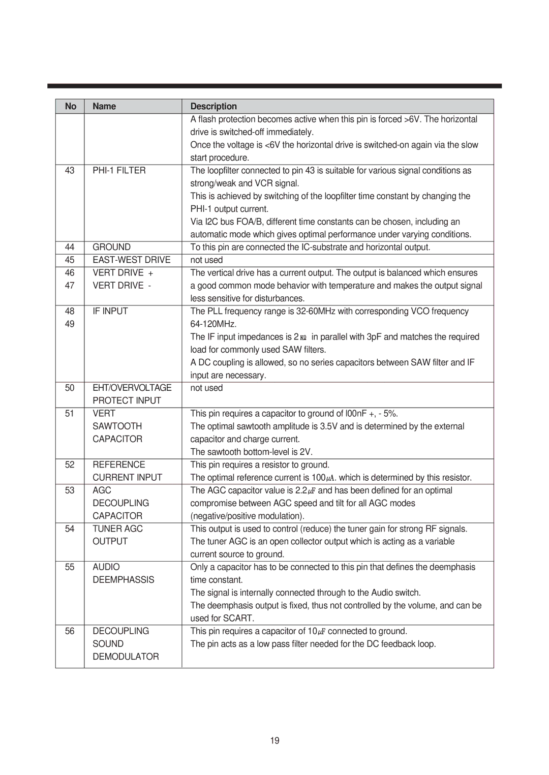
| A flash protection becomes active when this pin is forced >6V. The horizontal | |
|
| drive is |
|
|
| Once the voltage is <6V the horizontal drive is | |
|
| start procedure. |
|
|
|
| |
43 |
| The loopfilter connected to pin 43 is suitable for various signal conditions as | |
|
| strong/weak and VCR signal. |
|
|
| This is achieved by switching of the loopfilter time constant by changing the | |
|
|
| |
|
| Via I2C bus FOA/B, different time constants can be chosen, including an | |
|
| automatic mode which gives optimal performance under varying conditions. | |
|
|
| |
44 | GROUND | To this pin are connected the | |
|
|
|
|
45 |
| not used |
|
|
|
| |
46 | VERT DRIVE + | The vertical drive has a current output. The output is balanced which ensures | |
47 | VERT DRIVE - | a good common mode behavior with temperature and makes the output signal | |
|
| less sensitive for disturbances. |
|
|
|
| |
48 | IF INPUT | The PLL frequency range is | |
49 |
|
| |
|
| The IF input impedances is 2 in parallel with 3pF and matches the required | |
|
| load for commonly used SAW filters. |
|
|
| A DC coupling is allowed, so no series capacitors between SAW filter and IF | |
|
| input are necessary. |
|
|
|
|
|
50 | EHT/OVERVOLTAGE | not used |
|
| PROTECT INPUT |
|
|
|
|
| |
51 | VERT | This pin requires a capacitor to ground of l00nF +, - 5%. | |
| SAWTOOTH | The optimal sawtooth amplitude is 3.5V and is determined by the external | |
| CAPACITOR | capacitor and charge current. |
|
|
| The sawtooth |
|
|
|
| |
52 | REFERENCE | This pin requires a resistor to ground. | |
| CURRENT INPUT | The optimal reference current is 100 | . which is determined by this resistor. |
|
|
| |
53 | AGC | The AGC capacitor value is 2.2 and has been defined for an optimal | |
| DECOUPLING | compromise between AGC speed and tilt for all AGC modes | |
| CAPACITOR | (negative/positive modulation). |
|
|
|
| |
54 | TUNER AGC | This output is used to control (reduce) the tuner gain for strong RF signals. | |
| OUTPUT | The tuner AGC is an open collector output which is acting as a variable | |
|
| current source to ground. |
|
|
|
| |
55 | AUDIO | Only a capacitor has to be connected to this pin that defines the deemphasis | |
| DEEMPHASSIS | time constant. |
|
|
| The signal is internally connected through to the Audio switch. | |
|
| The deemphasis output is fixed, thus not controlled by the volume, and can be | |
|
| used for SCART. |
|
|
|
|
|
56 | DECOUPLING | This pin requires a capacitor of 10 | connected to ground. |
| SOUND | The pin acts as a low pass filter needed for the DC feedback loop. | |
| DEMODULATOR |
|
|
|
|
|
|
19