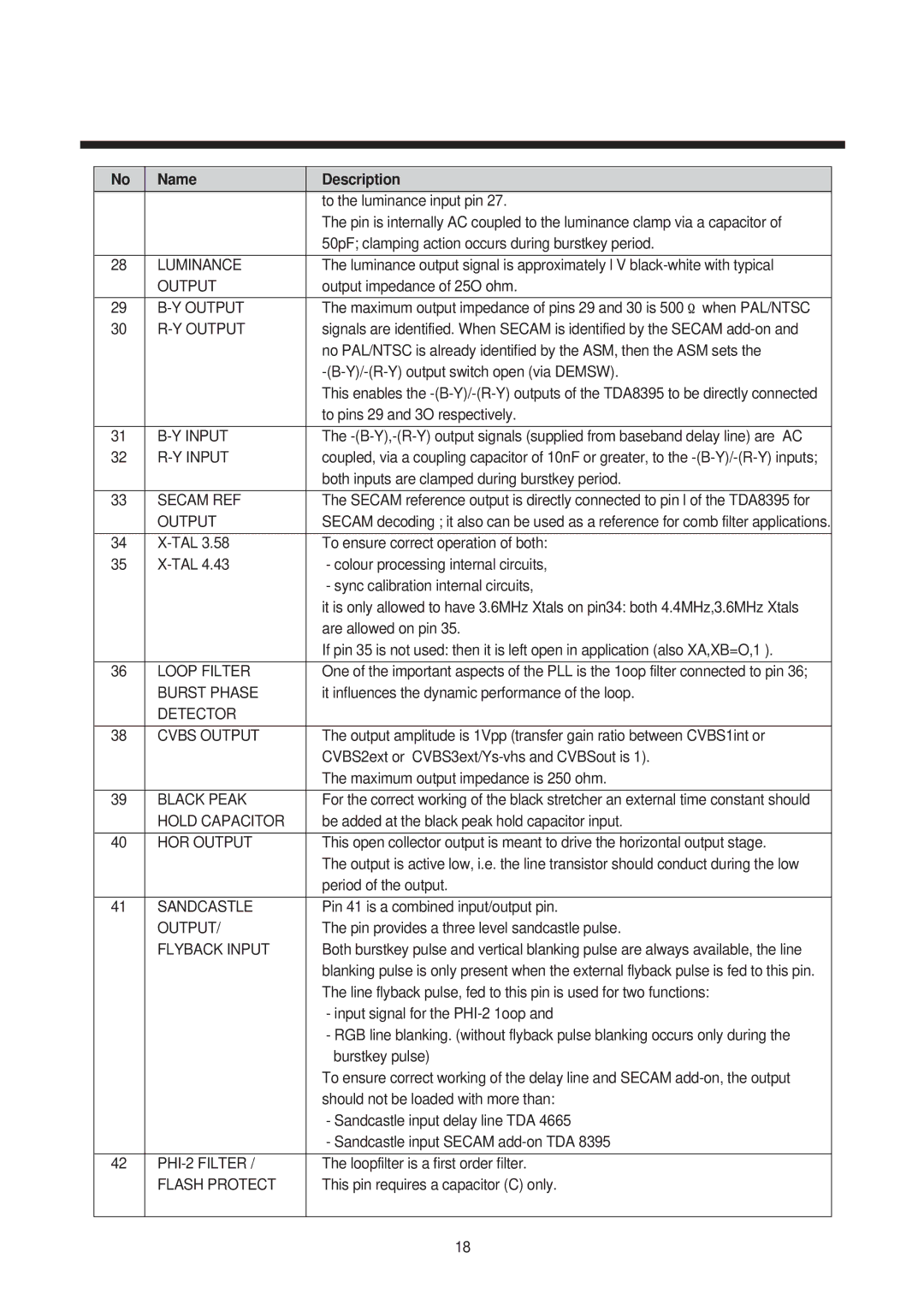
| No | Name | Description |
|
|
| to the luminance input pin 27. |
|
|
| The pin is internally AC coupled to the luminance clamp via a capacitor of |
|
|
| 50pF; clamping action occurs during burstkey period. |
|
|
| |
| 28 | LUMINANCE | The luminance output signal is approximately l V |
|
| OUTPUT | output impedance of 25O ohm. |
|
|
|
|
29 | The maximum output impedance of pins 29 and 30 is 500 when PAL/NTSC | ||
30 | signals are identified. When SECAM is identified by the SECAM | ||
|
|
| no PAL/NTSC is already identified by the ASM, then the ASM sets the |
|
|
| |
|
|
| This enables the |
|
|
| to pins 29 and 3O respectively. |
|
|
| |
| 31 | The | |
32 | coupled, via a coupling capacitor of 10nF or greater, to the | ||
|
|
| both inputs are clamped during burstkey period. |
|
|
| |
| 33 | SECAM REF | The SECAM reference output is directly connected to pin l of the TDA8395 for |
|
| OUTPUT | SECAM decoding ; it also can be used as a reference for comb filter applications. |
|
|
| |
| 34 | To ensure correct operation of both: | |
35 | - colour processing internal circuits, | ||
|
|
| - sync calibration internal circuits, |
|
|
| it is only allowed to have 3.6MHz Xtals on pin34: both 4.4MHz,3.6MHz Xtals |
|
|
| are allowed on pin 35. |
|
|
| If pin 35 is not used: then it is left open in application (also XA,XB=O,1 ). |
|
|
| |
| 36 | LOOP FILTER | One of the important aspects of the PLL is the 1oop filter connected to pin 36; |
|
| BURST PHASE | it influences the dynamic performance of the loop. |
|
| DETECTOR |
|
|
|
| |
| 38 | CVBS OUTPUT | The output amplitude is 1Vpp (transfer gain ratio between CVBS1int or |
|
|
| CVBS2ext or |
|
|
| The maximum output impedance is 250 ohm. |
|
|
| |
| 39 | BLACK PEAK | For the correct working of the black stretcher an external time constant should |
|
| HOLD CAPACITOR | be added at the black peak hold capacitor input. |
|
|
| |
| 40 | HOR OUTPUT | This open collector output is meant to drive the horizontal output stage. |
|
|
| The output is active low, i.e. the line transistor should conduct during the low |
|
|
| period of the output. |
|
|
| |
| 41 | SANDCASTLE | Pin 41 is a combined input/output pin. |
|
| OUTPUT/ | The pin provides a three level sandcastle pulse. |
|
| FLYBACK INPUT | Both burstkey pulse and vertical blanking pulse are always available, the line |
|
|
| blanking pulse is only present when the external flyback pulse is fed to this pin. |
|
|
| The line flyback pulse, fed to this pin is used for two functions: |
|
|
| - input signal for the |
|
|
| - RGB line blanking. (without flyback pulse blanking occurs only during the |
|
|
| burstkey pulse) |
|
|
| To ensure correct working of the delay line and SECAM |
|
|
| should not be loaded with more than: |
|
|
| - Sandcastle input delay line TDA 4665 |
|
|
| - Sandcastle input SECAM |
|
|
| |
| 42 | The loopfilter is a first order filter. | |
|
| FLASH PROTECT | This pin requires a capacitor (C) only. |
|
|
|
|
18