E. X-POSITION ADJUSTMENT
TEST POINTS | S/W PULSE TEST PIN | PATH ADJ. FIXTURE | |
|
| ||
ENVELOPE TEST PIN | PATH ADJ. FIXTURE | ||
| |||
|
|
| |
MEASURING EQUIPMENT | OSCILLOSCOPE |
| |
|
|
| |
ADJUSTMENT | VR CONTROL | PATH ADJ. FIXTURE | |
|
| ||
ADJUST BOSS | MAIN BASE. | ||
| |||
|
|
|
a. Connect the path adjustment fixture to PT01 of the MAIN CIRCUIT BOARD. b. Play back the ALIGNMENT TAPE (COLOR BAR ALIGNMENT).
c. Connect
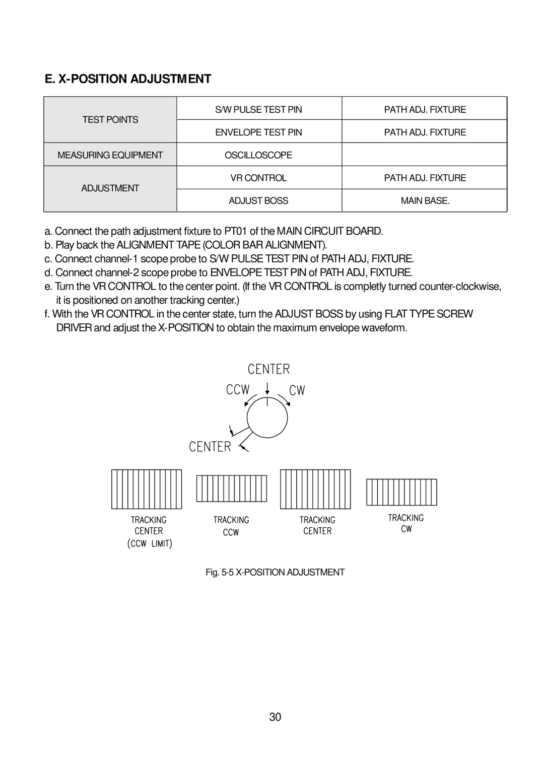
e. Turn the VR CONTROL to the center point. (If the VR CONTROL is completly turned
f. With the VR CONTROL in the center state, turn the ADJUST BOSS by using FLAT TYPE SCREW DRIVER and adjust the
Fig. 5-5 X-POSITION ADJUSTMENT
30