B. ADJUSTMENT OF THE A/C HEAD ASS'Y (TILT ADJUSTMENT)
a. Play back a
b. Adjust the A/C HEAD TILT SCREW untill the TAPE runs stable as shown in Fig.
C. ADJUSTMENT OF THE AUDIO AZIMUTH
(See Fig.5-3)
a. Play back the ALIGNMENT CASSETTE TAPE (NTSC: DN2 (SP, 7KHz), PAL: DP2 (SP, 6KHz)) b. Observe audio signals on an OSCILLOSCOPE.
c. Turn the A/C HEAD AZIMUTH SCREW to obtain the maximum audio output signal
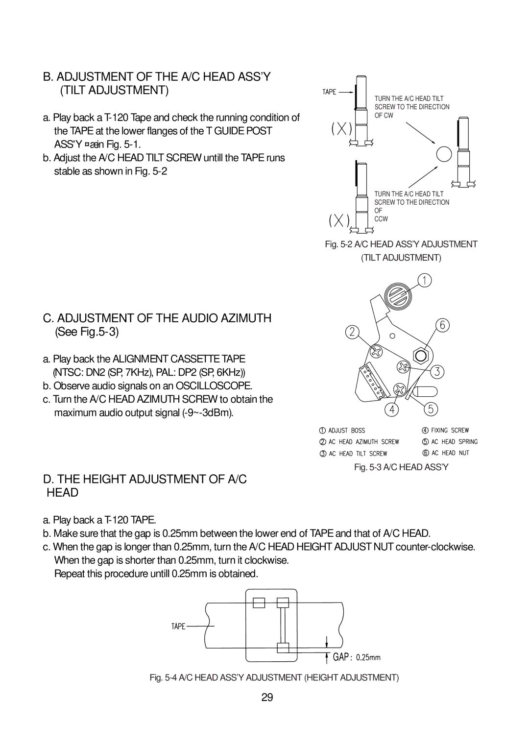
TURN THE A/C HEAD TILT
SCREW TO THE DIRECTION
OF CW
( )
|
| TURN THE A/C HEAD TILT | |
|
| SCREW TO THE DIRECTION | |
( | ) | OF | |
CCW | |||
|
|
Fig. 5-2 A/C HEAD ASS'Y ADJUSTMENT
(TILT ADJUSTMENT)
Fig. 5-3 A/C HEAD ASS'Y
D. THE HEIGHT ADJUSTMENT OF A/C
HEAD
a. Play back a
b. Make sure that the gap is 0.25mm between the lower end of TAPE and that of A/C HEAD.
c. When the gap is longer than 0.25mm, turn the A/C HEAD HEIGHT ADJUST NUT
Repeat this procedure untill 0.25mm is obtained.
GAP
Fig. 5-4 A/C HEAD ASS'Y ADJUSTMENT (HEIGHT ADJUSTMENT)
29