L. X-POSITION (See Fig. 5-11)
TEST POINTS | S/W PULSE TEST PIN | PATH ADJ. FIXTURE | |
|
| ||
ENVELOPE TEST PIN | PATH ADJ. FIXTURE | ||
| |||
|
|
| |
MEASURING EQUIPMENT | OSCILLOSCOPE |
| |
|
|
| |
ADJUSTMENT | VR CONTROL | PATH ADJ. FIXTURE | |
|
| ||
ADJUST BOSS | MAIN BASE. | ||
| |||
|
|
|
a. Connect the PATH ADJ. FIXTURE to PT01 of the MAIN CIRCUIT BOARD. b. Play back the ALIGNMENT TAPE (COLOR SIGNAL BAR).
c. Connect the
e. Adjust the VR CONTROL to the center position. (When the VR CONTROL is completely turned counter- clockwise, it is set at another tracking center position).
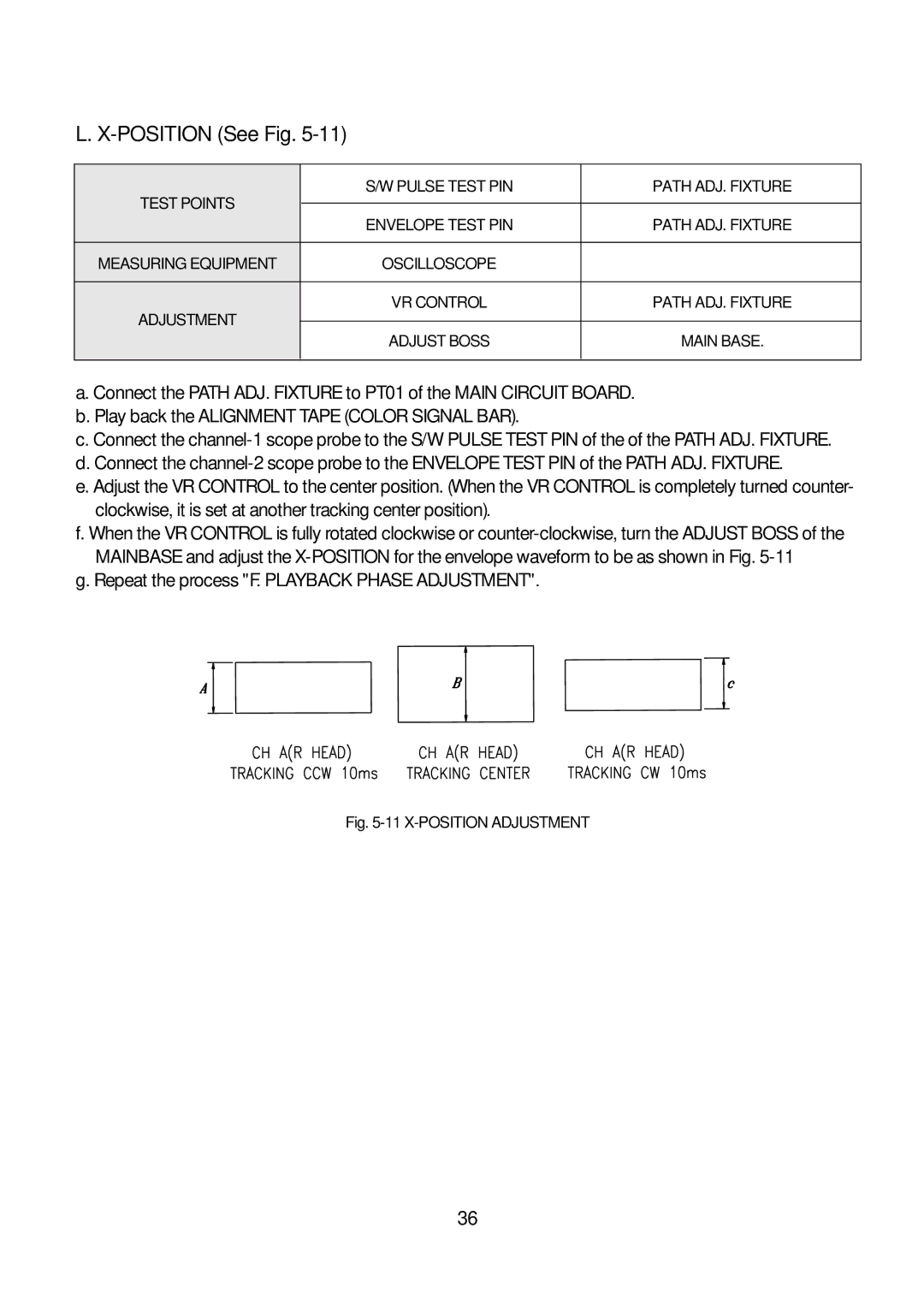
f. When the VR CONTROL is fully rotated clockwise or
g. Repeat the process "F. PLAYBACK PHASE ADJUSTMENT".
Fig. 5-11 X-POSITION ADJUSTMENT
36