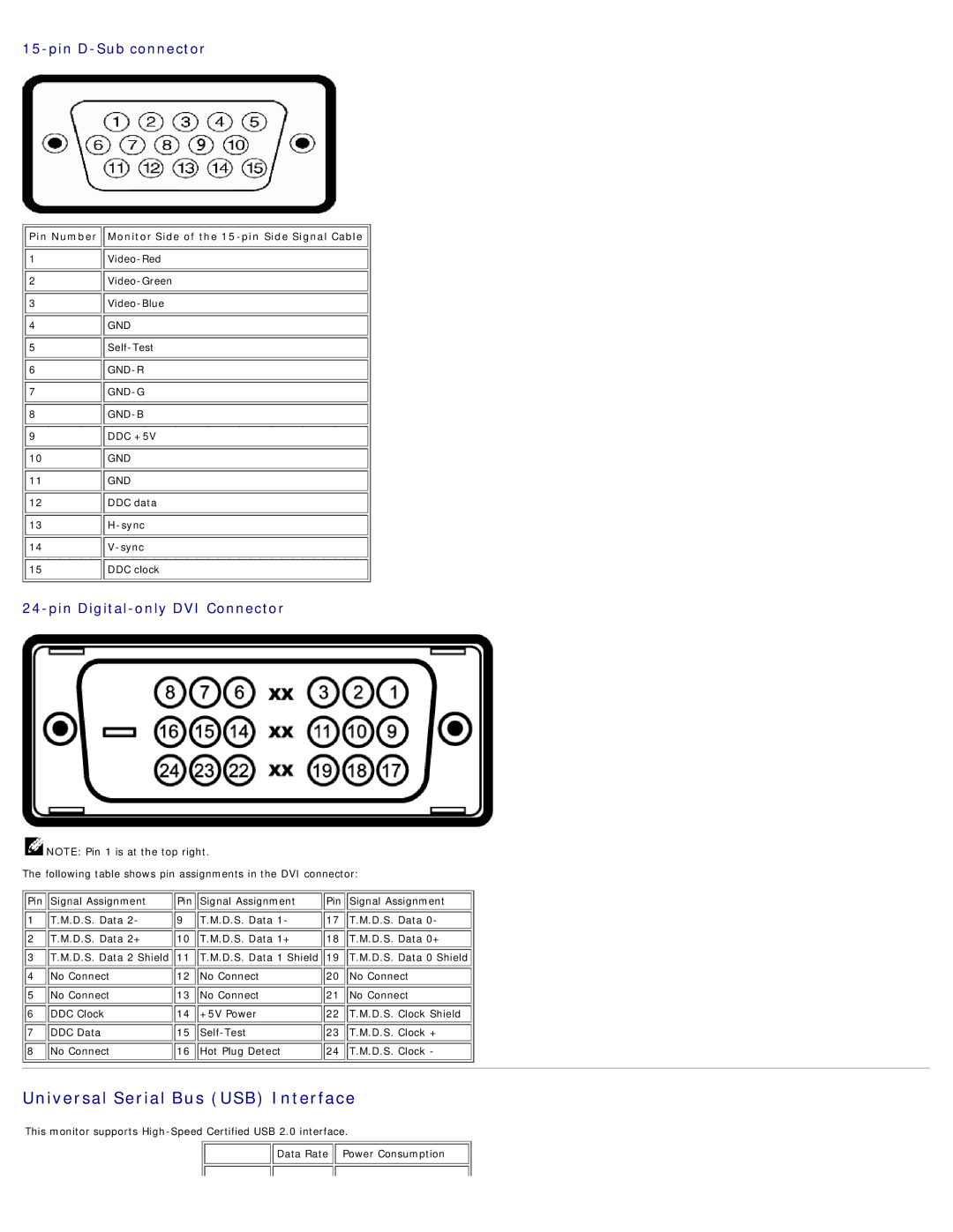
15-pin D-Sub connector
 Pin Number
 Monitor Side of the
 15-pin Side Signal Cable 
1 | |
2 | |
3 | |
4 | GND |
5 | |
6 | |
7 | |
8 | |
9 | DDC +5V |
10 | GND |
11 | GND |
12 | DDC data |
13 | |
14 | |
15 | DDC clock |
24-pin Digital-only DVI Connector
![]() NOTE: Pin 1 is at the top right.
NOTE: Pin 1 is at the top right.
The following table shows pin assignments in the DVI connector:
Pin | Signal Assignment | Pin | Signal Assignment | Pin | Signal Assignment |
1 | T.M.D.S. Data 2- | 9 | T.M.D.S. Data 1- | 17 | T.M.D.S. Data 0- |
2 | T.M.D.S. Data 2+ | 10 | T.M.D.S. Data 1+ | 18 | T.M.D.S. Data 0+ |
3 | T.M.D.S. Data 2 Shield | 11 | T.M.D.S. Data 1 Shield | 19 | T.M.D.S. Data 0 Shield |
4 | No Connect | 12 | No Connect | 20 | No Connect |
5 | No Connect | 13 | No Connect | 21 | No Connect |
6 | DDC Clock | 14 | +5V Power | 22 | T.M.D.S. Clock Shield |
7 | DDC Data | 15 | 23 | T.M.D.S. Clock + | |
8 | No Connect | 16 | Hot Plug Detect | 24 | T.M.D.S. Clock - |
Universal Serial Bus (USB) Interface
This monitor supports
![]()
![]() Data Rate
Data Rate ![]()
![]() Power Consumption
Power Consumption