W . d e l l . c o m s u p p o r t . d e l l . c o m
Service Tag
Diagnostic lights
CD or DVD eject button CD or DVD activity light
June YH242
Contents
Cleaning the Computer, Keyboard, and Monitor
Program is designed for an earlier Windows operating system
100
Using Microsoft Windows XP System Restore
Resolving Software and Hardware Incompatibilities
101
107
104
105
108
135
Finding Information
Warranty information
Support.dell.com
Updates
Use the Service Tag to
When you use
Appropriate for your configuration, providing critical
Click the topic that describes your problem
How to work with programs and files
How to personalize my desktop
How to reinstall my operating system
Finding Information
Setting Up and Using Your Computer
Front View of the Computer
Vents and any object near the vents
Computer. Instead, perform an operating system shutdown
Back View of the Computer
Computer
Back Panel Connectors
Green a good connection exists between a 10-Mbps network
Ensure reliable operation
Connecting Monitors
Surround sound setup
TV-OUT connector
Connecting Two Monitors With VGA Connectors
One DVI Connector
VGA connector blue
Connecting a Television TV
Changing the Display Settings
For dual-monitor capable cards with two DVI connectors
Setting Up a Printer
Connecting a USB Printer
Printer Cable
Connecting to the Internet
Setting Up Your Internet Connection
Setting Up a Home and Office Network
Connecting to a Network Adapter
Transferring Information to a New Computer
Network Setup Wizard
Network adapter connector
Computer Network cable
Setting Up and Using Your Computer
Setting Up and Using Your Computer
Playing CDs and DVDs
Playing a CD or DVD
Adjusting the Volume
CD player includes the following basic buttons
How to Copy a CD or DVD
Adjusting the Picture
Copying CDs and DVDs
Using Blank CDs and DVDs
Media Type Read Write Rewritable
Using a Media Card Reader Optional
Helpful Tips
XD-Picture Card Memory Stick MS/MS Pro
Ieee 1394 Optional
SmartMedia SMC MultiMediaCard MMC
Hibernate Mode
Power Management
Standby Mode
Overview
Power Options Properties
Power Schemes Tab
Advanced Tab
Cleaning Your Computer
Cleaning the Computer, Keyboard, and Monitor
Hibernate Tab
Cleaning the Floppy Drive
Cleaning the Mouse
Cleaning CDs and DVDs
Setting Up and Using Your Computer
Hyper-Threading
About Your RAID Configuration
Optimizing Performance
RAID Level 1 Configuration
RAID Level 0 Configuration
Segment Hard drive
Configuring Your Computer for RAID
Setting Your Computer to RAID-Enabled Mode
Using the Intel RAID Option ROM Utility
Creating a RAID Level 0 Configuration
Creating a RAID Level 1 Configuration
Using the Intel Application Accelerator
Deleting a RAID Volume
Creating a RAID Level 0 Configuration
Migrating to a RAID Level 0 Configuration
Migrating to a RAID Level 1 Configuration
Dell DataSafe Optional
Rebuilding a Degraded RAID Level 1 Configuration
Creating a Spare Hard Drive
Enabling the QRT Feature in the Operating system
Using Intel Viiv Quick Resume Technology QRT
Enabling the QRT Feature in System Setup
Intel Viiv Technology Optional
Optimizing Performance
Optimizing Performance
Drive Problems
Troubleshooting Tips
Battery Problems
Solving Problems
CD and DVD drive problems
Problems writing to a CD/DVD-RW drive
Mail, Modem, and Internet Problems
Hard drive problems
Error Messages
Use these characters in filenames
Media Card Reader Problems
Computer does not start up
Keyboard Problems
Lockups and Software Problems
Computer stops responding
Program is designed for an earlier Windows operating system
Program stops responding
Program crashes repeatedly
Solid blue screen appears
Memory Problems
Other software problems
Mouse Problems
Network Problems
Power Problems
Printer Problems
Scanner Problems
Sound and Speaker Problems
No sound from speakers
No sound from headphones
Video and Monitor Problems
Screen is blank
Screen is difficult to read
Solving Problems
Light Pattern Problem Description
Diagnostic Lights
Troubleshooting Tools
If available, install properly working
Light Pattern Problem Description Suggested Resolution
Identified a faulty module or
If the problem persists, contact Dell
Installed. If the computer starts
For memory module/connector
Placement exist see Memory on
Memory on
Dell Diagnostics
Option Function
Dell Diagnostics Main Menu
Tab Function
Identifying Drivers
What Is a Driver?
Drivers
Windows XP
Using Windows XP Device Driver Rollback
Reinstalling Drivers
Manually Reinstalling Drivers
Resolving Software and Hardware Incompatibilities
Using Microsoft Windows XP System Restore
Restoring Your Operating System
Enabling System Restore
Creating a Restore Point
Undoing the Last System Restore
Restoring the Computer to an Earlier Operating State
Using Dell PC Restore by Symantec
Removing Dell PC Restore
Troubleshooting Tools
Recommended Tools
Removing and Installing Parts
Before You Begin
Turning Off Your Computer
Removing the Computer Cover
Before Working Inside Your Computer
Cover release latch Computer cover
Power supply System board
Inside View of Your Computer
FlexBay USB connector Clear Cmos jumper
Battery socket Battery Sata Connectors SATA0
Front panel I/O connector Main power connector
System Board Components
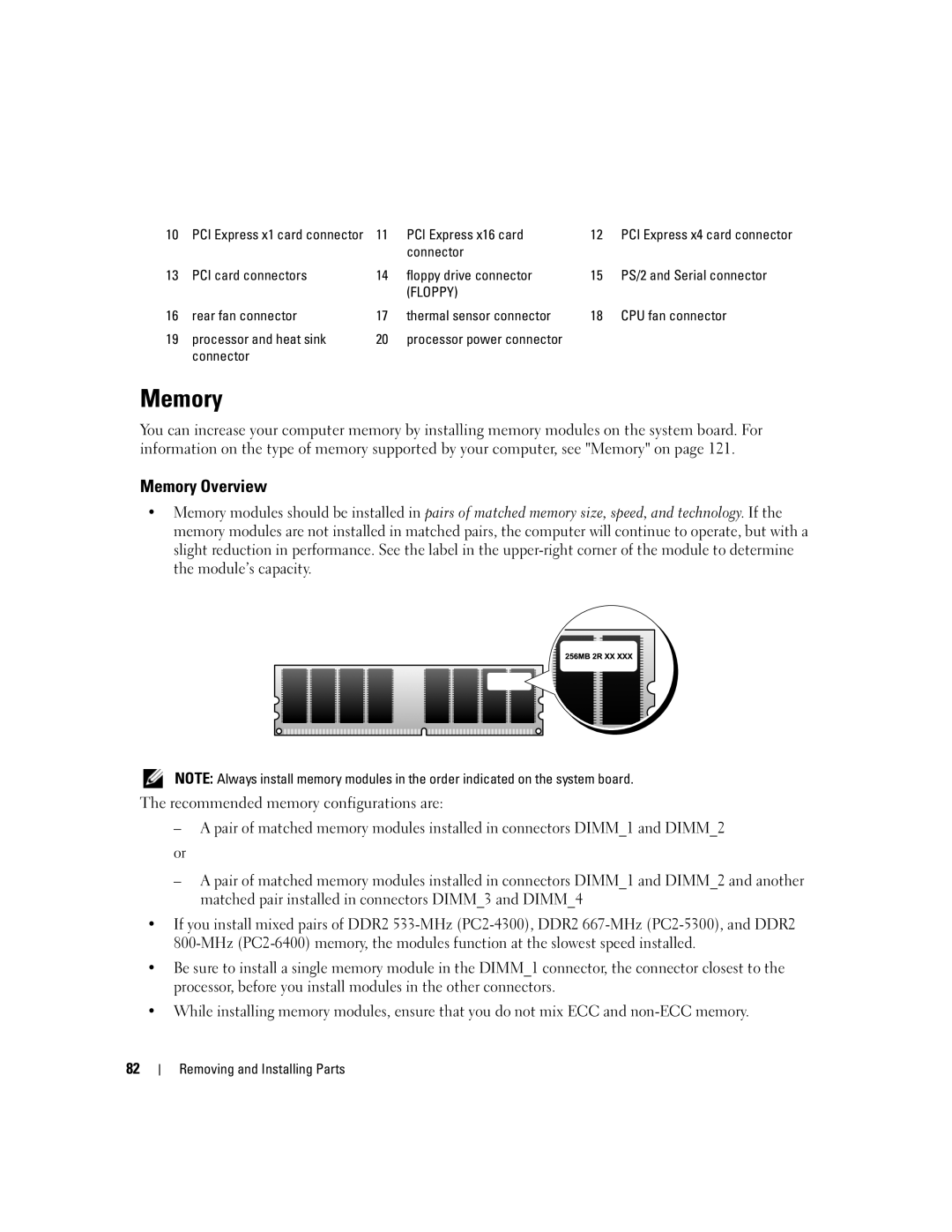
Memory Overview
Connector
Memory
PCI Express x16 card
Installing Memory
Addressing Memory With 4-GB Configurations
Crossbar Removing and Installing Parts
Cutouts Memory module
Removing Memory
Cards
Installing a PCI Card
PCI Cards
Release tabs Filler bracket
Release tab
Fully seated card Not fully seated card
Alignment bar Alignment guide
Removing a PCI Card
PCI Express Cards
Card retention door Release tabs
Installing a PCI Express Card
Filler bracket Alignment guide Alignment bar
Release tab
PCI Express x16 card slot
PCI Express x1 card PCI Express x1 card slot
Fully seated card Not fully seated card
Release tab
Removing a PCI Express Card
Release tab
Removing and Installing Parts
100
Drive Panels
Removing the Drive Panel
Sliding plate Sliding plate lever
101
Removing the Drive-Panel Insert
Drive panel Drive-panel insert tab
Center drive-panel tab Drive panel
Replacing the Drive-Panel Insert
102
Drive-panel insert
Replacing the Drive Panel
Drives
103
Hard Drive
General Installation Guidelines
104
Removing a Hard Drive
Installing a Hard Drive
Power cable
105
106
Adding a Second Hard Drive
107
Removing a Floppy Drive
Floppy Drive
108
Power cable Floppy drive cable
109
110
Installing a Floppy Drive
Floppy drive
Removing a Media Card Reader
Present on all computers Removing and Installing Parts
Media Card Reader
111
112
113
Installing a Media Card Reader
Media Card Reader
CD/DVD Drive
114
Removing a CD/DVD Drive
CD/DVD drive cable Power cable
115
116
Installing a CD/DVD Drive
CD/DVD drive
CD/DVD drive Power cable
117
Replacing the Battery
Battery
118
Replacing the Computer Cover
Battery Tab
119
120
Specifications
121
Audio
122
Expansion Bus
123
Connectors
Drives
Controls and Lights
Power
124
Product Information Guide
125
System Setup
Entering System Setup
Environmental
System Setup Screens
126
System Setup Options
127
128
Video
129
Increase in data transfer rates
130
Boot Sequence
From Suspend
Changing Boot Sequence for the Current Boot
Option Settings
131
Changing Boot Sequence for Future Boots
Clearing Forgotten Passwords
132
Clearing Cmos Settings
133
FCC Notice U.S. Only
Definition of Dell-Installed Software and Peripherals
Dell Technical Support Policy U.S. Only
Definition of Third-Party Software and Peripherals
Contacting Dell
135
136
137
138
139
140
141
142
143
144
145
146
147
148
149
Called from within Singapore or Malaysia only
150
Website support.ap.dell.com
151
152
153
Printers, and Projectors for Relationship
154
155
156
157
Glossary
158
159
160
161
162
NIC See network adapter
163
164
165
166
Index
Index 167
168 Index
Index 169
USB
170 Index