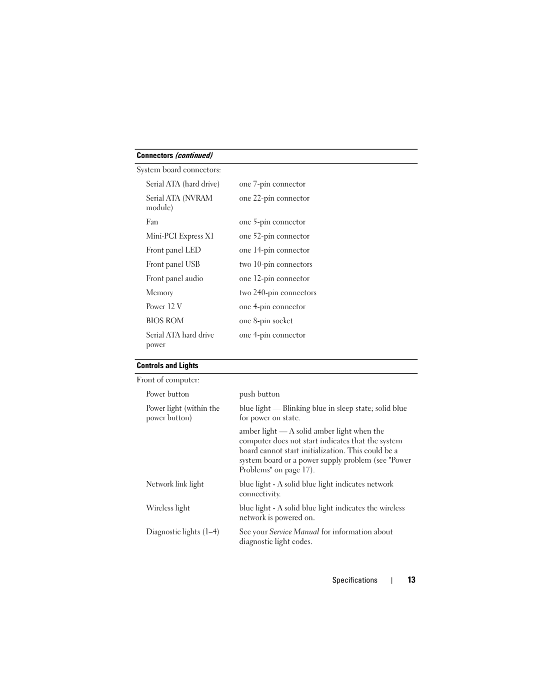
Connectors (continued)
System board connectors:
Serial ATA (hard drive) | one |
Serial ATA (NVRAM | one |
module) |
|
Fan | one |
one | |
Front panel LED | one |
Front panel USB | two |
Front panel audio | one |
Memory | two |
Power 12 V | one |
BIOS ROM | one |
Serial ATA hard drive | one |
power |
|
|
|
Controls and Lights |
|
|
|
Front of computer: |
|
Power button | push button |
Power light (within the | blue light — Blinking blue in sleep state; solid blue |
power button) | for power on state. |
| amber light — A solid amber light when the |
| computer does not start indicates that the system |
| board cannot start initialization. This could be a |
| system board or a power supply problem (see "Power |
| Problems" on page 17). |
Network link light | blue light - A solid blue light indicates network |
| connectivity. |
Wireless light | blue light - A solid blue light indicates the wireless |
| network is powered on. |
Diagnostic lights | See your Service Manual for information about |
| diagnostic light codes. |
Specifications
13
