L400 specifications
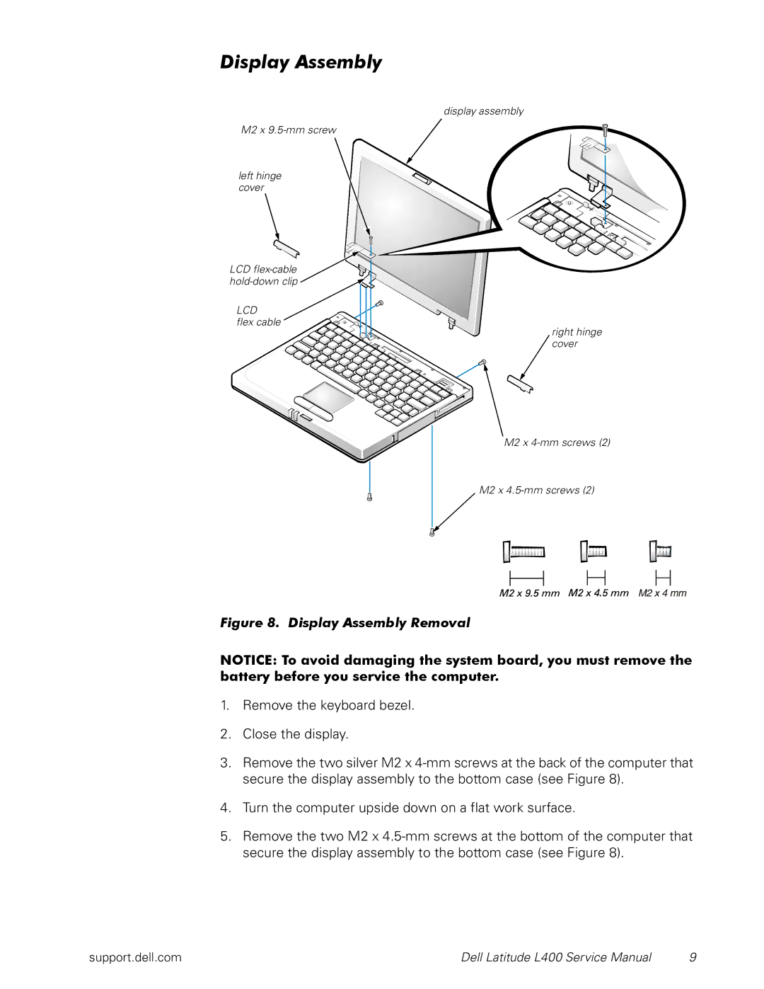
The Dell L400 is a notable laptop that emerged in the late 1990s, specifically designed for business professionals and mobile users. This portable computer was celebrated for its lightweight design and solid performance during an era when mobile computing was starting to gain traction.One of the key features of the Dell L400 is its compact size. Weighing in at just around four pounds, it was easy to carry, making it an ideal choice for users who needed to travel. Its 12.1-inch display was a notable aspect, featuring an active matrix screen that provided decent visual clarity for its time, thus enhancing the mobile computing experience. The display, although small by today’s standards, was designed for convenience and portability, balancing screen size with overall weight.
The L400 was powered by Intel's Pentium III processor, which delivered respectable performance for everyday tasks such as word processing, spreadsheets, and basic multimedia applications. This made it suitable for professionals who required a reliable device for work-related activities without the latest specifications of modern laptops. Additionally, it commonly featured between 64 to 128 MB of RAM, upgradeable, which allowed users to run multiple applications smoothly.
Storage options included traditional hard drives ranging from 6 to 20 GB, providing ample space for documents and essential software of the era. While this may seem limited compared to modern standards, it was a reasonable capacity for users at that time.
In terms of connectivity, the L400 integrated essential ports such as USB, parallel, and serial, catering to a variety of peripherals that users often employed. It also included an Ethernet port for network connectivity, which was crucial for business environments. The inclusion of a modem facilitated dial-up internet connections, reflecting the technology landscape of the late 90s.
Battery life was another significant attribute, as the Dell L400 offered decent longevity that allowed users to extend productivity without being tethered to a power outlet. It typically featured a lithium-ion battery that contributed to its portability.
Overall, the Dell L400 stands out as a historical example of early portable computing, marked by its balance of performance, portability, and connectivity. While it may not compete with modern laptops in terms of specifications, its design and functionality marked an important step in the evolution of mobile computing technology.

