Back to Contents Page
System Board Layout
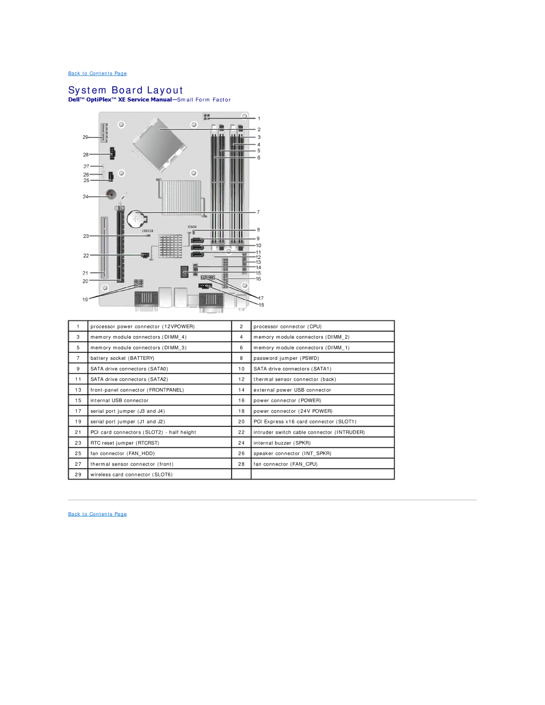
Dell™ OptiPlex™ XE Service
1 | processor power connector (12VPOWER) | 2 | processor connector (CPU) |
|
|
|
|
3 | memory module connectors (DIMM_4) | 4 | memory module connectors (DIMM_2) |
|
|
|
|
5 | memory module connectors (DIMM_3) | 6 | memory module connectors (DIMM_1) |
|
|
|
|
7 | battery socket (BATTERY) | 8 | password jumper (PSWD) |
|
|
|
|
9 | SATA drive connectors (SATA0) | 10 | SATA drive connectors (SATA1) |
|
|
|
|
11 | SATA drive connectors (SATA2) | 12 | thermal sensor connector (back) |
|
|
|
|
13 | 14 | external power USB connector | |
|
|
|
|
15 | internal USB connector | 16 | power connector (POWER) |
|
|
|
|
17 | serial port jumper (J3 and J4) | 18 | power connector (24V POWER) |
|
|
|
|
19 | serial port jumper (J1 and J2) | 20 | PCI Express x16 card connector (SLOT1) |
|
|
|
|
21 | PCI card connectors (SLOT2) - half height | 22 | intruder switch cable connector (INTRUDER) |
|
|
|
|
23 | RTC reset jumper (RTCRST) | 24 | internal buzzer (SPKR) |
|
|
|
|
25 | fan connector (FAN_HDD) | 26 | speaker connector (INT_SPKR) |
|
|
|
|
27 | thermal sensor connector (front) | 28 | fan connector (FAN_CPU) |
|
|
|
|
29 | wireless card connector (SLOT6) |
|
|
|
|
|
|