REPAIRS
REPLACING THE POWER SUPPLY CABLE
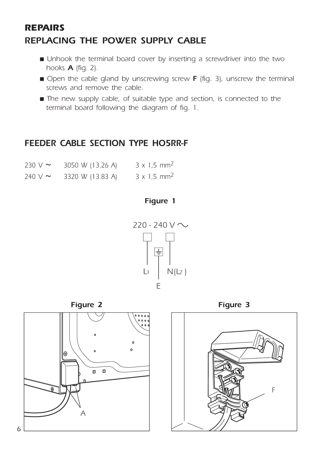
■Unhook the terminal board cover by inserting a screwdriver into the two hooks A (fig. 2).
■Open the cable gland by unscrewing screw F (fig. 3), unscrew the terminal screws and remove the cable.
■The new supply cable, of suitable type and section, is connected to the terminal board following the diagram of fig. 1.
FEEDER CABLE SECTION TYPE HO5RR-F
230 | V ~ | 3050 | W (13.26 | A) | 3 | x 1,5 | mm2 |
240 | V ~ | 3320 | W (13.83 | A) | 3 | x 1,5 | mm2 |
Figure 1
220 - 240 V ![]()
6
|
|
|
|
|
|
|
|
|
|
|
|
|
|
|
|
|
|
|
|
|
|
|
|
| L1 |
|
| N(L2 ) | |||
|
|
|
|
|
|
|
|
|
|
| E | ||||
Figure 2 |
|
|
|
| Figure 3 | ||
F
A
