ELECTRIC DIAGRAM
Figure 4
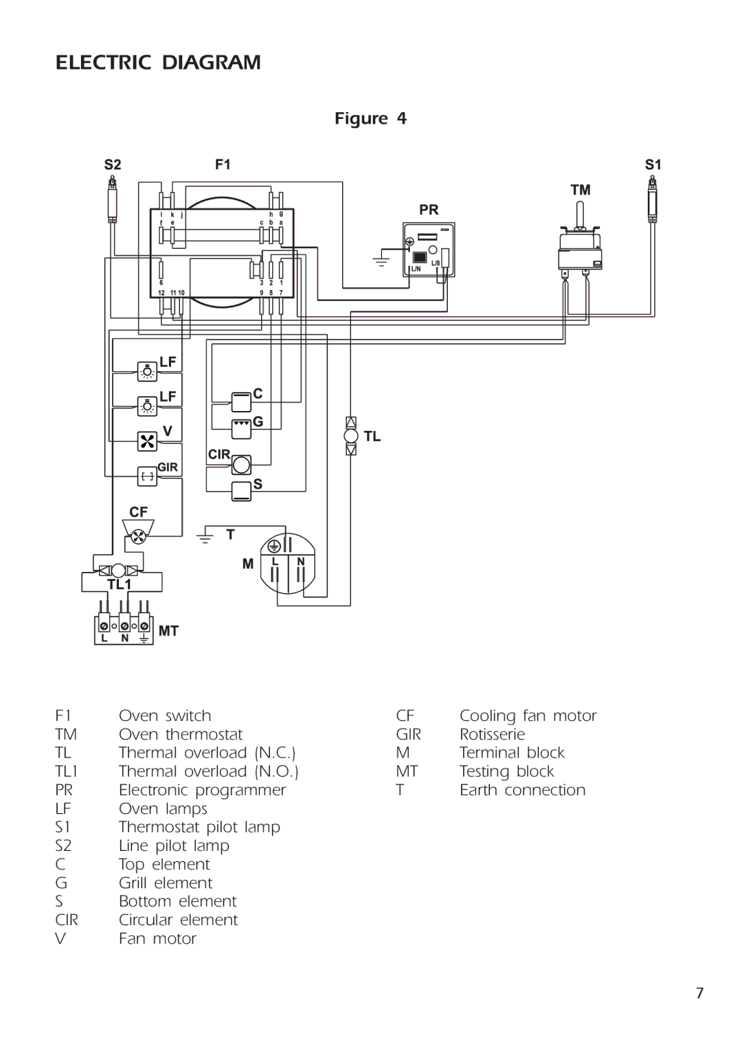
F1 | Oven switch | CF | Cooling fan motor |
TM | Oven thermostat | GIR | Rotisserie |
TL | Thermal overload (N.C.) | M | Terminal block |
TL1 | Thermal overload (N.O.) | MT | Testing block |
PR | Electronic programmer | T | Earth connection |
LF | Oven lamps |
|
|
S1 | Thermostat pilot lamp |
|
|
S2 | Line pilot lamp |
|
|
CTop element
G Grill element
S Bottom element
CIR | Circular element |
V | Fan motor |
7