EXTENSION AND SWITCH ASSEMBLY
ASSEMBLING CAST IRON EXTENSION
WING (MODEL
DISCONNECT MACHINE FROM POWER
C
SOURCE.
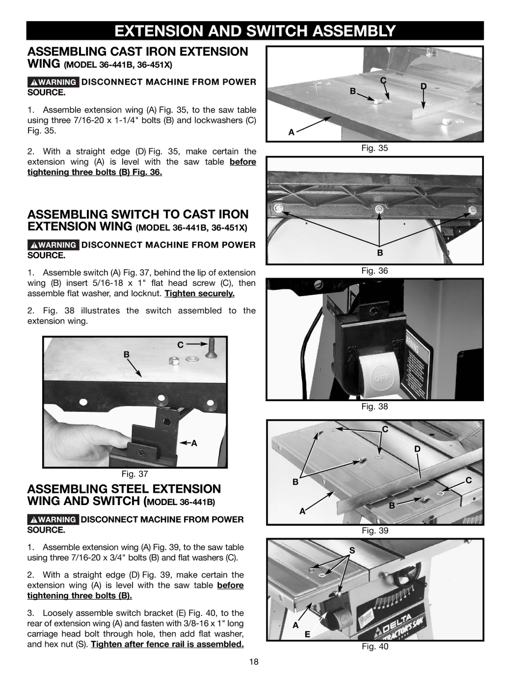
1.Assemble extension wing (A) Fig. 35, to the saw table using three
B
A ![]()
D
2.With a straight edge (D) Fig. 35, make certain the extension wing (A) is level with the saw table before tightening three bolts (B) Fig. 36.
ASSEMBLING SWITCH TO CAST IRON EXTENSION WING
 DISCONNECT MACHINE FROM POWER SOURCE.
1.Assemble switch (A) Fig. 37, behind the lip of extension wing (B) insert
2.Fig. 38 illustrates the switch assembled to the extension wing.
C
B
![]() A
A
Fig. 37
ASSEMBLING STEEL EXTENSION
Fig. 35
B |
Fig. 36
Fig. 38
![]() C
C
D
BC
WING AND SWITCH (MODEL 36-441B)
DISCONNECT MACHINE FROM POWER
A
B ![]()
SOURCE.
1.Assemble extension wing (A) Fig. 39, to the saw table using three
2.With a straight edge (D) Fig. 39, make certain the extension wing (A) is level with the saw table before tightening three bolts (B).
3.Loosely assemble switch bracket (E) Fig. 40, to the rear of extension wing (A) and fasten with
Fig. 39
S
A
E
Fig. 40
18