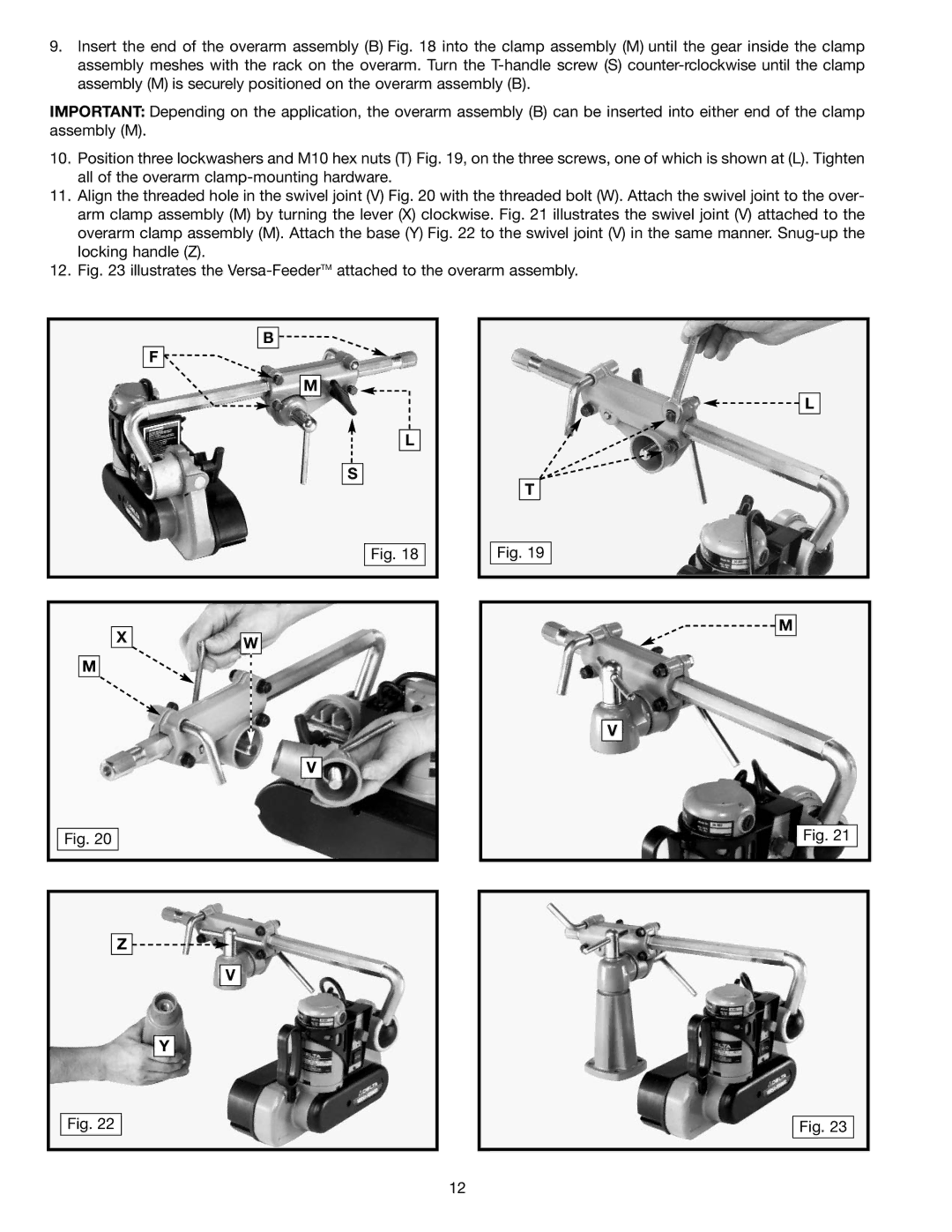
9.Insert the end of the overarm assembly (B) Fig. 18 into the clamp assembly (M) until the gear inside the clamp assembly meshes with the rack on the overarm. Turn the
IMPORTANT: Depending on the application, the overarm assembly (B) can be inserted into either end of the clamp assembly (M).
10.Position three lockwashers and M10 hex nuts (T) Fig. 19, on the three screws, one of which is shown at (L). Tighten all of the overarm
11.Align the threaded hole in the swivel joint (V) Fig. 20 with the threaded bolt (W). Attach the swivel joint to the over- arm clamp assembly (M) by turning the lever (X) clockwise. Fig. 21 illustrates the swivel joint (V) attached to the overarm clamp assembly (M). Attach the base (Y) Fig. 22 to the swivel joint (V) in the same manner.
12.Fig. 23 illustrates the
B ![]()
F ![]()
M
L
S
Fig. 18
XW
M
V
Fig. 20
Z ![]()
![]()
V
![]()
![]() L
L
T
Fig. 19
![]()
![]() M
M
V
Fig. 21
Y
Fig. 22
Fig. 23
12
