ASSEMBLING EXTENSION WING
NOTE: CHECK TO SEE WHAT TYPE OF STARTER BOX WAS SHIPPED WITH YOUR SAW (GPE OR LVC). A GPE STARTER HAS ROUND “ON” AND “OFF” BUTTONS. A LVC STARTER HAS RECTANGLE “ON” AND “OFF” BUTTONS.
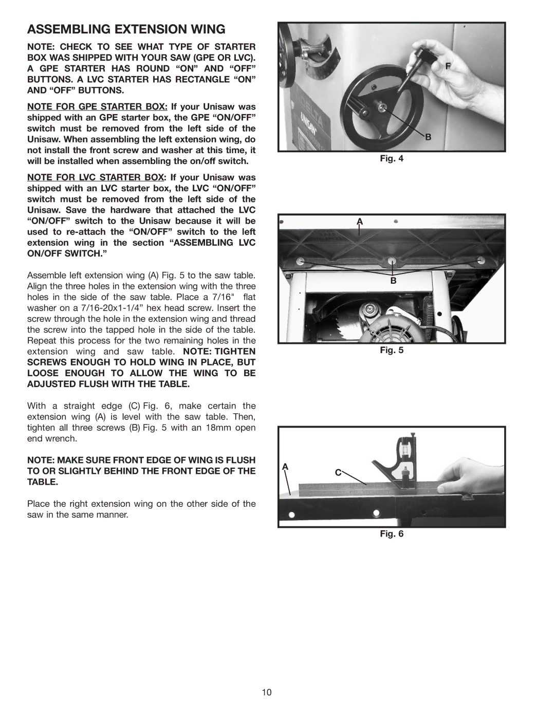
NOTE FOR GPE STARTER BOX: If your Unisaw was shipped with an GPE starter box, the GPE “ON/OFF” switch must be removed from the left side of the Unisaw. When assembling the left extension wing, do not install the front screw and washer at this time, it will be installed when assembling the on/off switch.
NOTE FOR LVC STARTER BOX: If your Unisaw was shipped with an LVC starter box, the LVC “ON/OFF” switch must be removed from the left side of the Unisaw. Save the hardware that attached the LVC “ON/OFF” switch to the Unisaw because it will be used to
Assemble left extension wing (A) Fig. 5 to the saw table. Align the three holes in the extension wing with the three holes in the side of the saw table. Place a 7/16" flat washer on a
F
B
Fig. 4
A |
B |
extension wing and saw table. NOTE: TIGHTEN
SCREWS ENOUGH TO HOLD WING IN PLACE, BUT LOOSE ENOUGH TO ALLOW THE WING TO BE ADJUSTED FLUSH WITH THE TABLE.
With a straight edge (C) Fig. 6, make certain the extension wing (A) is level with the saw table. Then, tighten all three screws (B) Fig. 5 with an 18mm open end wrench.
NOTE: MAKE SURE FRONT EDGE OF WING IS FLUSH TO OR SLIGHTLY BEHIND THE FRONT EDGE OF THE TABLE.
Place the right extension wing on the other side of the saw in the same manner.
A
Fig. 5
C![]()
Fig. 6
10