A![]()
B![]()
![]() D
D
Fig. 16
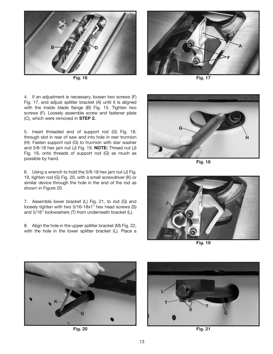
4.If an adjustment is necessary, loosen two screws (F) Fig. 17, and adjust splitter bracket (A) until it is aligned with the inside blade flange (B) Fig. 15. Tighten two screws (F). Loosely assemble screw and fastener plate (C), which were removed in STEP 2.
5.Insert threaded end of support rod (G) Fig. 18, through slot in rear of saw and into hole in rear trunnion
(H). Fasten support rod (G) to trunnion with star washer and
6.Using a wrench to hold the
7.Assemble lower bracket (L) Fig. 21, to rod (G) and loosely tighten with two
8.Align the hole in the upper splitter bracket (M) Fig. 22, with the hole in the lower splitter bracket (L). Place a
K![]()
G
Fig. 20
A
![]() F
F
Fig. 17
G![]()
H
Fig. 18
J
Fig. 19
L![]()
T
T
S
G
Fig. 21
13
