ASSEMBLING LVC STARTER BOX TO CABINET
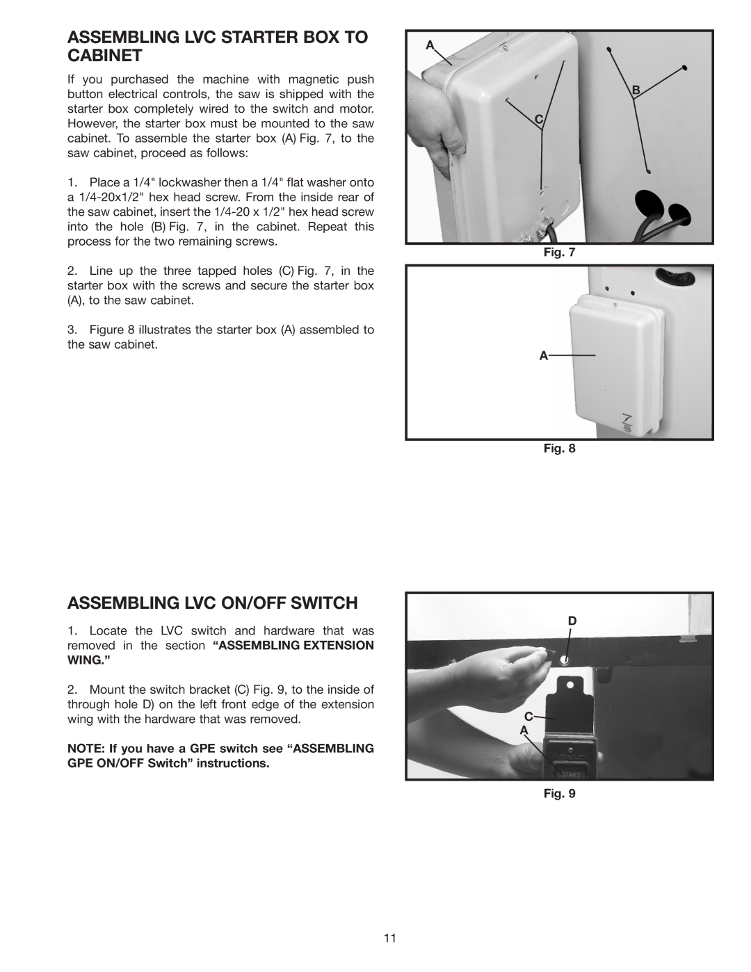
If you purchased the machine with magnetic push button electrical controls, the saw is shipped with the starter box completely wired to the switch and motor. However, the starter box must be mounted to the saw cabinet. To assemble the starter box (A) Fig. 7, to the saw cabinet, proceed as follows:
1.Place a 1/4" lockwasher then a 1/4" flat washer onto a
2.Line up the three tapped holes (C) Fig. 7, in the starter box with the screws and secure the starter box (A), to the saw cabinet.
3.Figure 8 illustrates the starter box (A) assembled to the saw cabinet.
A
B
C
Fig. 7
A
Fig. 8
ASSEMBLING LVC ON/OFF SWITCH
1.Locate the LVC switch and hardware that was removed in the section “ASSEMBLING EXTENSION
WING.”
2.Mount the switch bracket (C) Fig. 9, to the inside of through hole D) on the left front edge of the extension wing with the hardware that was removed.
NOTE: If you have a GPE switch see “ASSEMBLING GPE ON/OFF Switch” instructions.
D
C![]()
A
Fig. 9
11
