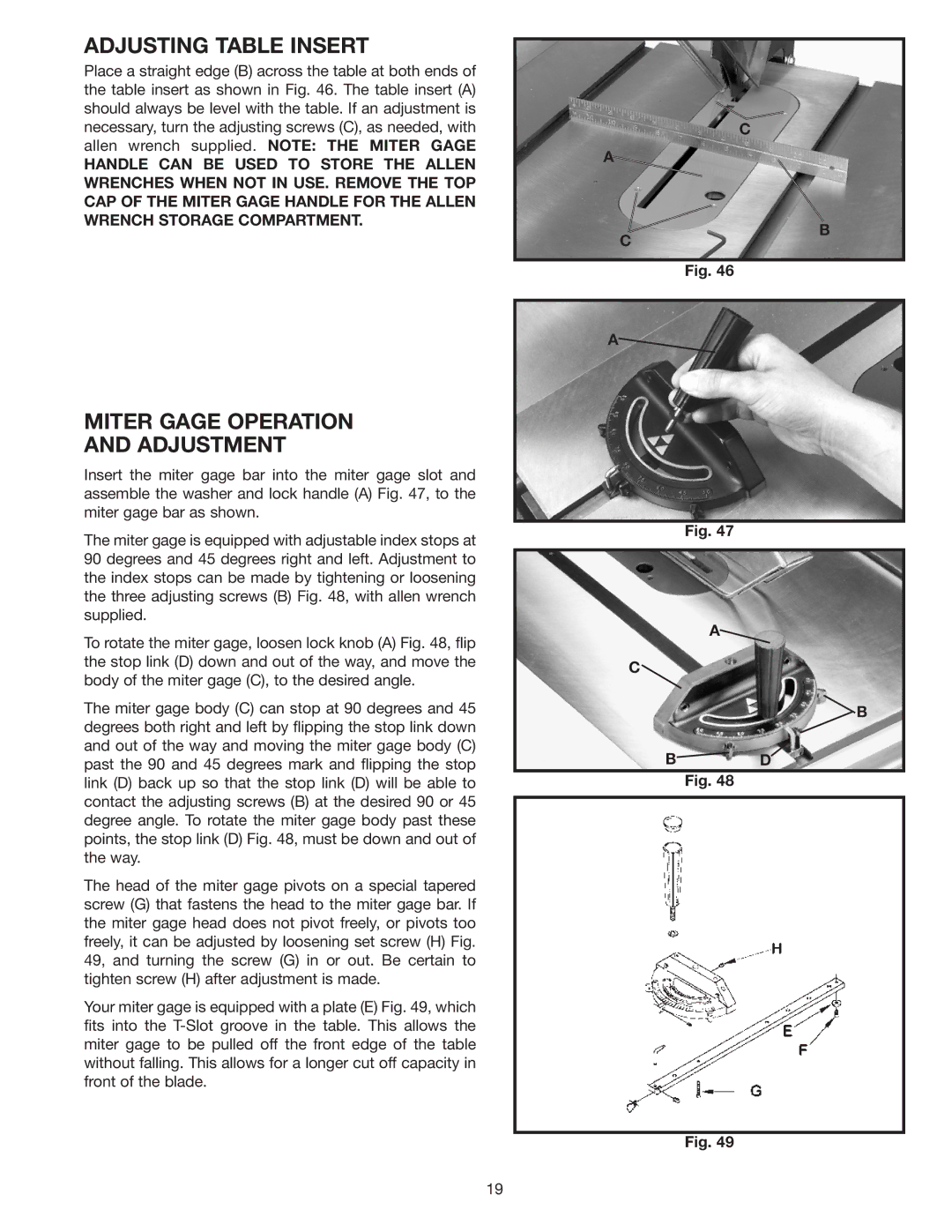
ADJUSTING TABLE INSERT
Place a straight edge (B) across the table at both ends of the table insert as shown in Fig. 46. The table insert (A) should always be level with the table. If an adjustment is necessary, turn the adjusting screws (C), as needed, with allen wrench supplied. NOTE: THE MITER GAGE
HANDLE CAN BE USED TO STORE THE ALLEN WRENCHES WHEN NOT IN USE. REMOVE THE TOP CAP OF THE MITER GAGE HANDLE FOR THE ALLEN WRENCH STORAGE COMPARTMENT.
C
A![]()
C
B
MITER GAGE OPERATION
AND ADJUSTMENT
Insert the miter gage bar into the miter gage slot and assemble the washer and lock handle (A) Fig. 47, to the miter gage bar as shown.
The miter gage is equipped with adjustable index stops at 90 degrees and 45 degrees right and left. Adjustment to the index stops can be made by tightening or loosening the three adjusting screws (B) Fig. 48, with allen wrench supplied.
To rotate the miter gage, loosen lock knob (A) Fig. 48, flip the stop link (D) down and out of the way, and move the body of the miter gage (C), to the desired angle.
The miter gage body (C) can stop at 90 degrees and 45 degrees both right and left by flipping the stop link down and out of the way and moving the miter gage body (C) past the 90 and 45 degrees mark and flipping the stop link (D) back up so that the stop link (D) will be able to contact the adjusting screws (B) at the desired 90 or 45 degree angle. To rotate the miter gage body past these points, the stop link (D) Fig. 48, must be down and out of the way.
The head of the miter gage pivots on a special tapered screw (G) that fastens the head to the miter gage bar. If the miter gage head does not pivot freely, or pivots too freely, it can be adjusted by loosening set screw (H) Fig. 49, and turning the screw (G) in or out. Be certain to tighten screw (H) after adjustment is made.
Your miter gage is equipped with a plate (E) Fig. 49, which fits into the
Fig. 46
A
Fig. 47
A![]()
C![]()
![]() B
B
B![]() D
D
Fig. 48
Fig. 49
19