TAILSTOCK
![]() To reduce the risk of injury, tighten all screws and levers securely when adjusting any part of the lathe.
To reduce the risk of injury, tighten all screws and levers securely when adjusting any part of the lathe.
ADJUSTING TAILSTOCK
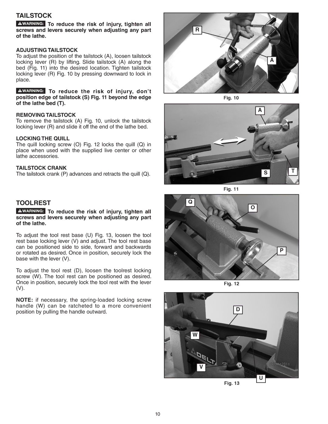
To adjust the position of the tailstock (A), loosen tailstock locking lever (R) by lifting. Slide tailstock (A) along the bed (Fig. 11) into the desired location. Tighten tailstock locking lever (R) Fig. 10 by pressing downward to lock in place.
![]() To reduce the risk of injury, don’t position edge of tailstock (S) Fig. 11 beyond the edge of the lathe bed (T).
To reduce the risk of injury, don’t position edge of tailstock (S) Fig. 11 beyond the edge of the lathe bed (T).
REMOVING TAILSTOCK
To remove the tailstock (A) Fig. 10, unlock the tailstock locking lever (R) and slide it off the end of the lathe bed.
LOCKING THE QUILL
The quill locking screw (O) Fig. 12 locks the quill (Q) in place when used with the supplied live center or other lathe accessories.
TAILSTOCK CRANK
The tailstock crank (P) advances and retracts the quill (Q).
TOOLREST
![]() To reduce the risk of injury, tighten all screws and levers securely when adjusting any part of the lathe.
To reduce the risk of injury, tighten all screws and levers securely when adjusting any part of the lathe.
To adjust the tool rest base (U) Fig. 13, loosen the tool rest base locking lever (V) and adjust. The tool rest base can be positioned side to side, forward and backwards or rotated as desired. Once in position, securely lock the base with the lever (V).
To adjust the tool rest (D), loosen the toolrest locking screw (W). The tool rest can be positioned as desired. Once in position, securely lock the tool rest with the lever
(V).
NOTE: if necessary, the
R
A
Fig. 10
A
|
| T |
S | ||
|
|
|
Fig. 11
Q
O
P
Fig. 12
D |
W |
V |
U |
Fig. 13
10
