10.Place new belt on spindle pulley making sure grooves in belt align with grooves in pulley.
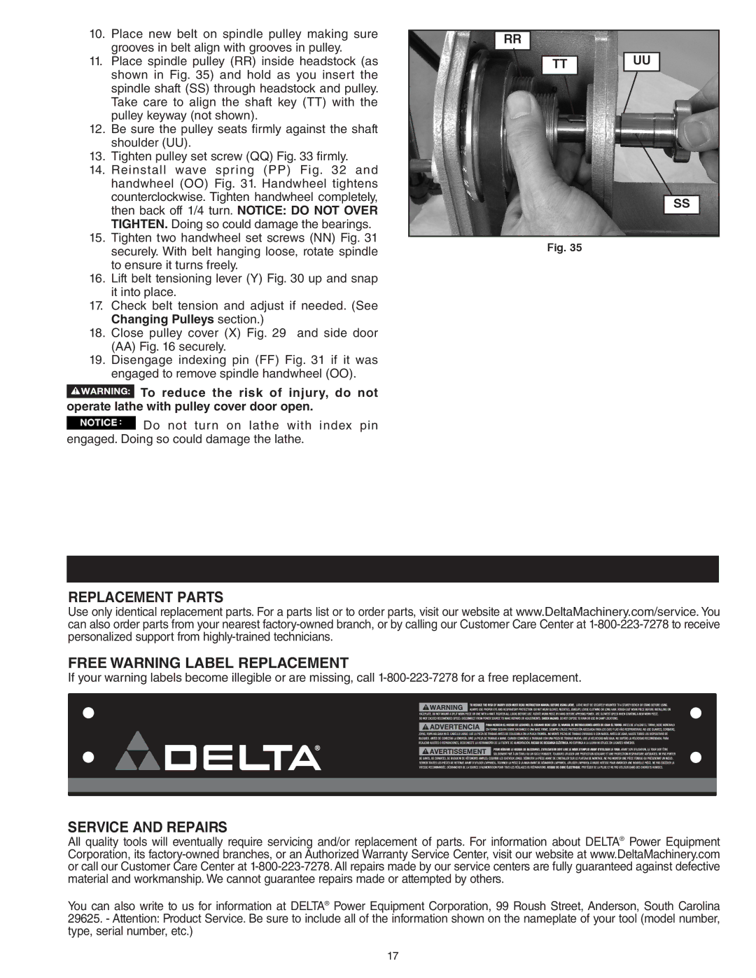
11.Place spindle pulley (RR) inside headstock (as shown in Fig. 35) and hold as you insert the spindle shaft (SS) through headstock and pulley. Take care to align the shaft key (TT) with the pulley keyway (not shown).
12.Be sure the pulley seats firmly against the shaft shoulder (UU).
13.Tighten pulley set screw (QQ) Fig. 33 firmly.
14.Reinstall wave spring (PP) Fig. 32 and handwheel (OO) Fig. 31. Handwheel tightens counterclockwise. Tighten handwheel completely, then back off 1/4 turn. NOTICE: DO NOT OVER TIGHTEN. Doing so could damage the bearings.
15.Tighten two handwheel set screws (NN) Fig. 31 securely. With belt hanging loose, rotate spindle to ensure it turns freely.
16.Lift belt tensioning lever (Y) Fig. 30 up and snap it into place.
17.Check belt tension and adjust if needed. (See Changing Pulleys section.)
18.Close pulley cover (X) Fig. 29 and side door (AA) Fig. 16 securely.
19.Disengage indexing pin (FF) Fig. 31 if it was engaged to remove spindle handwheel (OO).
![]() To reduce the risk of injury, do not operate lathe with pulley cover door open.
To reduce the risk of injury, do not operate lathe with pulley cover door open.
Do not turn on lathe with index pin engaged. Doing so could damage the lathe.
RR
|
| UU |
TT | ||
|
|
|
SS
Fig. 35
REPLACEMENT PARTS
Use only identical replacement parts. For a parts list or to order parts, visit our website at www.DeltaMachinery.com/service. You can also order parts from your nearest
FREE WARNING LABEL REPLACEMENT
If your warning labels become illegible or are missing, call
SERVICE AND REPAIRS
All quality tools will eventually require servicing and/or replacement of parts. For information about DELTA® Power Equipment Corporation, its
You can also write to us for information at DELTA® Power Equipment Corporation, 99 Roush Street, Anderson, South Carolina 29625. - Attention: Product Service. Be sure to include all of the information shown on the nameplate of your tool (model number, type, serial number, etc.)
17
