STARTING AND STOPPING THE TOOL
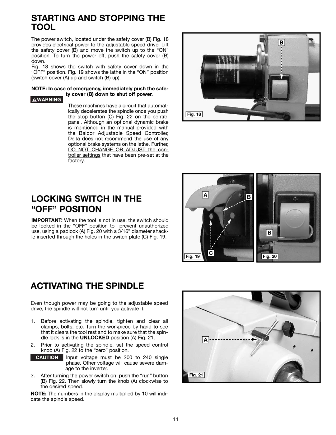
The power switch, located under the safety cover (B) Fig. 18 provides electrical power to the adjustable speed drive. Lift the safety cover (B) and move the switch up to the “ON” position. To turn the power off, push the safety cover (B) down.
Fig. 18 shows the switch with safety cover down in the “OFF” position. Fig. 19 shows the lathe in the “ON” position (switch cover (A) up and switch (B) up).
NOTE: In case of emergency, immediately push the safe- ty cover (B) down to shut off power.
These machines have a circuit that automat- ically decelerates the spindle once you push the stop button (C) Fig. 22 on the control panel. Although an optional dynamic brake is mentioned in the manual provided with the Baldor Adjustable Speed Controller, Delta does not recommend the use of any optional brake systems on the lathe. Further, DO NOT CHANGE OR ADJUST the con- troller settings that have been pre-set at the factory.
LOCKING SWITCH IN THE “OFF” POSITION
IMPORTANT: When the tool is not in use, the switch should be locked in the “OFF” position to prevent unauthorized use, using a padlock (A) Fig. 20 with a 3/16” diameter shack- le inserted through the holes in the switch plate (C) Fig. 19.
B
Fig. 18
| A | B |
|
| |
|
| B |
Fig. 19 |
| C |
| Fig. 20 |
ACTIVATING THE SPINDLE
Even though power may be going to the adjustable speed drive, the spindle will not turn until you activate it.
1.Before activating the spindle, tighten and clear all clamps, bolts, etc. Turn the workpiece by hand to see that it clears the tool rest and to make sure that the spin- dle lock is in the UNLOCKED position (A) Fig. 21.
2.Prior to activating the spindle, set the speed control knob (A) Fig. 22 to the “zero” position.
![]() Input voltage must be 200 to 240 single phase. Other voltage will cause severe dam- age to the inverter.
Input voltage must be 200 to 240 single phase. Other voltage will cause severe dam- age to the inverter.
3.After turning the power switch on, push the “run” button
(B)Fig. 22. Then slowly turn the knob (A) clockwise to the desired speed.
NOTE: The numbers in the display multiplied by 10 will indi- cate the spindle speed.
A ![]()
Fig. 21
11
