B |
A |
Fig. 74 |
B ![]()
A ![]()
Fig. 75
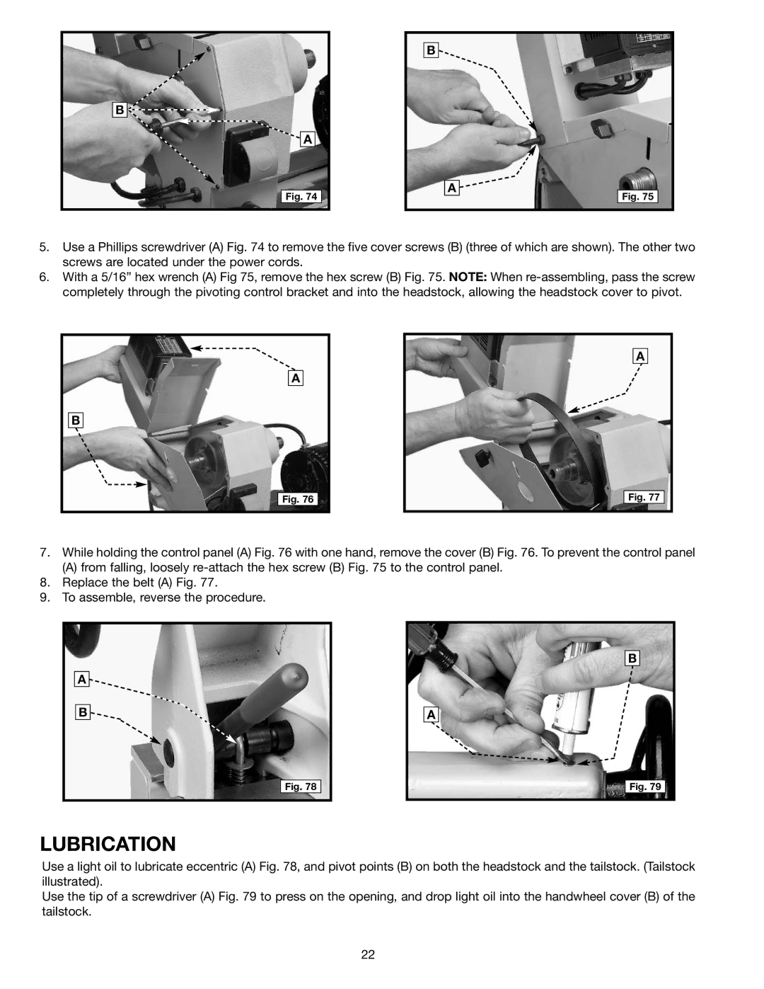
5.Use a Phillips screwdriver (A) Fig. 74 to remove the five cover screws (B) (three of which are shown). The other two screws are located under the power cords.
6.With a 5/16” hex wrench (A) Fig 75, remove the hex screw (B) Fig. 75. NOTE: When
A |
B |
Fig. 76 |
A
Fig. 77
7.While holding the control panel (A) Fig. 76 with one hand, remove the cover (B) Fig. 76. To prevent the control panel
(A) from falling, loosely
8.Replace the belt (A) Fig. 77.
9.To assemble, reverse the procedure.
A ![]()
B ![]()
Fig. 78
B |
A |
Fig. 79 |
LUBRICATION
Use a light oil to lubricate eccentric (A) Fig. 78, and pivot points (B) on both the headstock and the tailstock. (Tailstock illustrated).
Use the tip of a screwdriver (A) Fig. 79 to press on the opening, and drop light oil into the handwheel cover (B) of the tailstock.
22
