ADJUSTING THE MITER GAUGE SLOT PARALLEL WITH THE SANDING DISC
DISCONNECT MACHINE FROM POWER SOURCE.
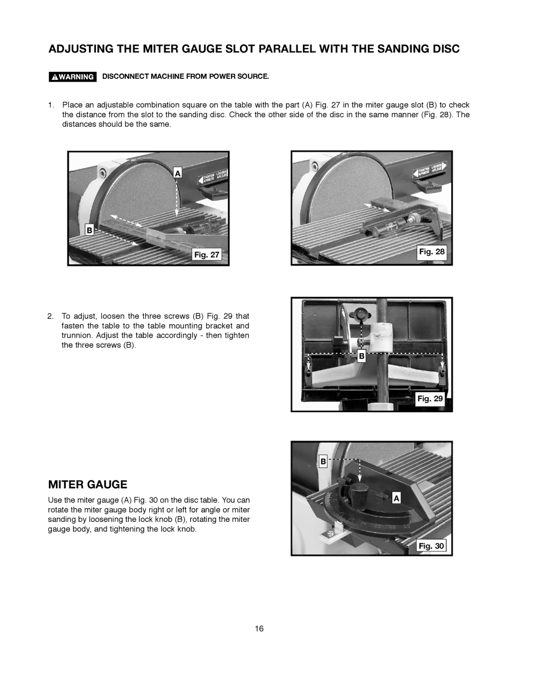
1.Place an adjustable combination square on the table with the part (A) Fig. 27 in the miter gauge slot (B) to check the distance from the slot to the sanding disc. Check the other side of the disc in the same manner (Fig. 28). The distances should be the same.
A
B ![]()
| Fig. 28 | |
Fig. 27 | ||
| ||
|
|
2.To adjust, loosen the three screws (B) Fig. 29 that fasten the table to the table mounting bracket and trunnion. Adjust the table accordingly - then tighten the three screws (B).
MITER GAUGE
B
Fig. 29
B ![]()
Use the miter gauge (A) Fig. 30 on the disc table. You can rotate the miter gauge body right or left for angle or miter sanding by loosening the lock knob (B), rotating the miter gauge body, and tightening the lock knob.
A
Fig. 30
16