Manuals
/
Delta Electronics
/
Computer Equipment
/
Power Supply
Delta Electronics
Series E36SR Thermal Considerations, Thermal Curves, Thermal Testing Setup
Models:
Series E36SR
1
10
15
15
Download
15 pages
23.45 Kb
7
8
9
10
11
12
13
14
Specs
Warranty
Output Voltage Adjustment TRIM
Thermal Testing Setup
Safety
Features
Page 10
Image 10
Page 9
Page 11
Page 10
Image 10
Page 9
Page 11
Contents
FEATURES
DC/DC Power Modules 18~75V in, 5V/15A out
Delphi Series E36SR, 75W Eighth Brick Family
OPTIONS
OUTPUT CHARACTERISTICS
TECHNICAL SPECIFICATIONS
INPUT CHARACTERISTICS
DYNAMIC CHARACTERISTICS
ELECTRICAL CHARACTERISTICS CURVES
Figure 4 Turn-on transient at full rated load current CC mode
current 25%-50% of Io, max di/dt = 0.1A/µs. Load cap 10µF
tantalum capacitor and 1µF ceramic capacitor. Top Trace Vout
Figure 12 Input reflected ripple current, is, through a 12µH
DESIGN CONSIDERATIONS
Safety Considerations
Soldering and Cleaning Considerations
Input Source Impedance
Over-Voltage Protection
FEATURES DESCRIPTIONS
Over-Current Protection
Over-Temperature Protection
Rtrim − down = 511Δ − 10.2KΩ
FEATURES DESCRIPTIONS CON
Output Voltage Adjustment TRIM
Rtrim − up =
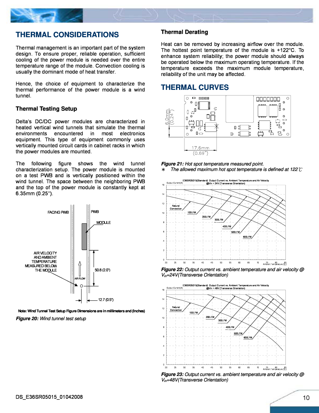
THERMAL CURVES
Thermal Testing Setup
THERMAL CONSIDERATIONS
Thermal Derating
RECOMMENDED PAD LAYOUT SMD
PICK AND PLACE LOCATION
SURFACE-MOUNT TAPE & REEL
Temp
LEADED Sn/Pb PROCESS RECOMMEND TEMP. PROFILE
LEAD FREE SAC PROCESS RECOMMEND TEMP. PROFILE
Time
Through-hole module
MECHANICAL DRAWING
Surface-mount module
Name
MECHANICAL DRAWING WITH HEATSPREADER
THROUGH-HOLE MODULE
WARRANTY
PART NUMBERING SYSTEM
MODEL LIST
MODEL NAME
Top
Page
Image
Contents