AVR-1802/882
Nous vous remercions pour l’achat de cet appareil
English Francais
Safety Instructions
Table of Contents
Before Using
Features
Part Names and Functions
Front Panel
Remote control unit
System System SET UP
Finally, setting up the system
Setting UP the Speaker Systems
Read this First
Line Line OUT
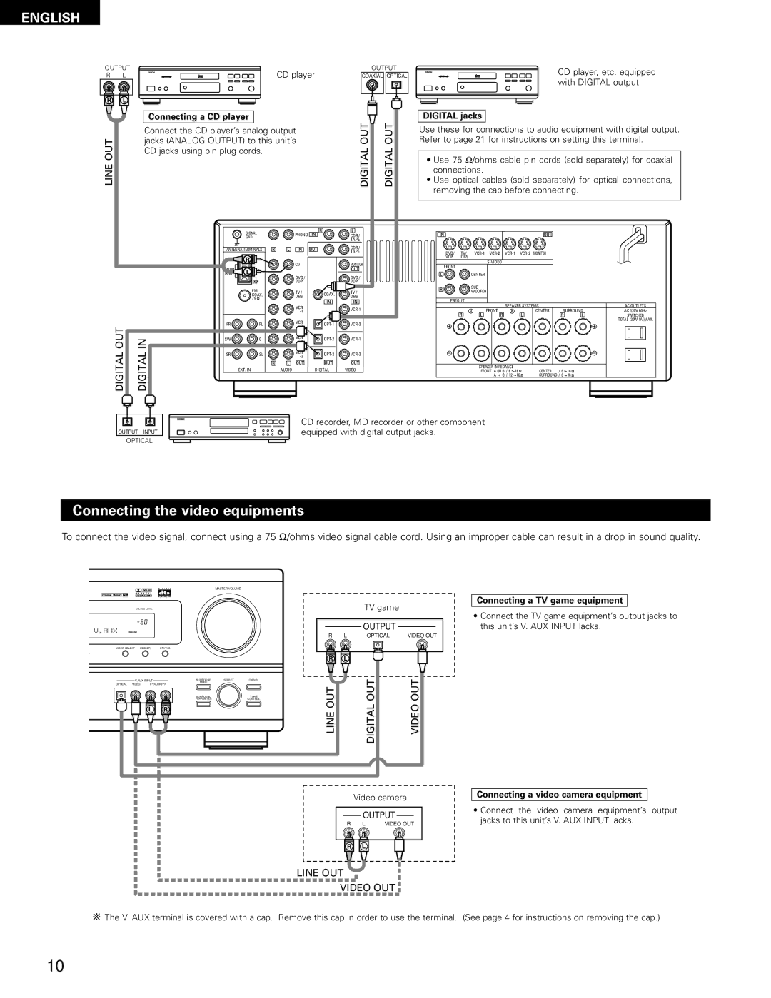
Connecting the audio components
Connections
Front Subwoofer Center Surround Line OUT
Connecting the video equipments
Connecting a video decks
Connecting a TV/DBS tuner
Connecting a DVD player or a video disc player VDP
Connecting the audio output jacks
Connecting a monitor TV
Connecting a video component equipped with S-video jacks
Precaution when using S-jacks
Connecting the video decks
AM loop antenna assembly Connection of AM antennas
Connecting the antenna terminals
FM antenna adapter assembly
Precautions when connecting speakers
Connecting the speaker cords
Connecting banana plugs
Speaker system connections
Protector circuit
Range of operation of the remote control unit
Using the Remote Control Unit
Inserting the batteries
System Setup button
Setting UP the System
Use the following buttons to set up the system
Cursor buttons , ª, 0
Setting the speaker configuration
Before setting up the system
Press the System button to enter the setting
Subwoofer mode
Setting the Subwoofer Mode
Assignment of low frequency signal range
Parameters
Preparations
Setting the delay time
Listening position
After setting up the system
Digital input setup
Terminal
Operating Denon audio components
Remote Control Unit
Preset memory Audio component
For tape deck Tape
Preset memory Video component
For video disc player VDP
Operating a video component stored in the preset memory
For DVD player
For video deck VCR
Operation
Check that all connections are proper Turn on the power
Remote control unit to turn on the power
Before operating
Input mode selection function
To select the input mode from main unit
To select the input mode from the remote control unit
Playing the input source
Dolby Digital
Adjusting the sound quality tone
After starting playback
DTS
Turning the sound off temporarily muting
Listening over headphones
Checking the currently playing program source, etc
Playback using the external input EXT. in jacks
Mode AUTO, PCM, DTS or Analog button to switch to
Before playing with the surround function
Adjust the level of the selected speaker
Surround
Digital or DTS modes
Dolby Surround Pro Logic II mode
Dolby PRO Logic
Dimension setting
Cinema EQ setting
Panorama setting
Center Width setting
Position of the slide switch on
Set the input mode to Auto or DTS
Select the Dolby/DTS Surround mode
Remote control unit
Surround parameters w Cinema EQ. Cinema Equalizer
Use left and right buttons to set the D. COMP. Initial
Use left and right buttons to set the LFE level
COMP. Dynamic Range Compression
Video Game
Surround modes and their features
DSP Surround Simulation
Personal Memory Plus
Use Left Right buttons to set the room size Initial
DSP surround simulation
Use Left Right buttons to set the effect level Initial
Delay 30ms
Use Left Right buttons to set the delay time Initial
When turned counterclockwise
When turned clockwise
Press Surround Parameter
Surround parameters e
Surround modes and parameters
Auto preset memory
Listening to the Radio
Manual tuning
Auto tuning
Press Tuner to set the input function to Tuner
Preset stations
Recalling preset stations
Last Function Memory
Initialization of the Microprocessor
Additional Information
Speaker setting examples
Surround
Dolby Digital compatible media and playback methods
Dolby Digital and Dolby Pro Logic
Dolby Pro Logic
DTS Digital Surround
DTS compatible media and playback methods
Troubleshooting
Specifications
Avant de mettre sous tension
Table DES Matieres
Avant L‘UTILISATION
Ranger ces instructions dans un endroit sûr
Precautions DE Manipulation
Precautions D’INSTALLATION
Caracteristiques
Nomenclature ET Fonctions
Panneau avant
Unité de télécommande
System SET UP
Lire EN Premier
Ensuite, insérer les piles dans la télécommande
Finalement, configurer le système
Réglage DES Systèmes D’ENCEINTE
Mettre cet appareil sous tension. Dans ce cas, mettre cet
Connexions
Connexion des composants audio
Audio. Ne pas les utiliser pour un sèche-cheveux, etc
Prises numériques Digital
Connexion des composants vidéo
Connexion d’un lecteur de CD
Connexion d’un jeu vidéo
Platine vidéo
Connexion d’un téléviseur/tuner DBS Téléviseur/DBS
Prise de sortie de moniteur Monitor
Connexion des lecteurs vidéo
Remarque à propos des prises en S
Connexion d’un composant vidéo équipé de prises vidéo S
Précautions d’utilisation des prises en S
Remarques
Remarque à l’installateur de système de télédistribution
Connexion des bornes d’antennes
Ensemble d’antenne-cadre AM Connexion des antennes AM
Connexions du système d’enceintes
Connexion des bornes d’enceinte
Circuit de protection
Plage d’utilisation de la télécommande
Utilisation DE LA Télécommande
Insertion des piles
Touches Cursor , ª, 0
Installation DU Systeme
Touche System Setup
Touche Select
Appuyer sur la touche System pour accéder aux réglages
Avant de configurer le système
Configuration des haut-parleurs
Touche gauche
Précaution
Réglage de la sortie de graves Subwoofer Mode
Paramètres
Utiliser les touches gauche Et droit
Reglage de la temps de retard
Préparations
Optique 2 OPT Initial
Configuration de l’entrée numérique
Apres avoir configure le système
PHONO, Tuner et V. AUX ne peuvent pas être sélectionnés
Mémoire préréglée Composants audio
Unite DE Telecommande
Utilisation des composants audio Denon
Pour platine cassette Tape
Mémoire préréglée Composants vidéo
Pour platine vidéo VCR
Pour lecteur DVD
Pour lecteur de vidéodisque VDP
Pour moniteur de téléviseur
Avant l’utilisation
Préparatifs
Lecture de la source de programme analogique
Réglage de la qualité sonore tonalité
Après le début de la lecture
Réglé est sélectionné, tourner le bouton
Muting
Ecoute avec casque
Désactivation provisoire du son sourdine
Video Select
Pour choisir le mode d’entrée souhaîté. Voir
Annulation du mode d’ entrée externe
Sur le bouton Input Mode AUTO, PCM, DTS ou Analog
Lecture en utilisant les prises d’entrée externe EXT.
Tone
Ambiance
Avant la lecture utilisant la fonction d’ambiance
Ajuster le niveau de l’enceinte sélectionnée
Mode Dolby Surround Pro Logic
Exemple
Paramètres d’ambiance q Mode Pro Logic
Réglage Dimension
Réglage Default
Mode Panorama
Glissière de la télécommande est en
Régler le mode d’entrée à Auto ou DTS
Sélectionner le mode Dolby/DTS Surround
Sélectionner la source d’entrée
COMP. Compression de gamme dynamique
Paramètres d’ambiance w Cinema EQ. Eqaliseur Cinéma
LFE Effet de basse fréquence
Modes d’ambiance et leurs caractéristiques
Simulation D’AMBIANCE DSP
Mémoire personnelle Plus
Simulation d’ambiance DSP
Touche gauche Touche droit
Default Y/N
Lorsqu’il est tourné dans le sens anti-horaire
Lorsqu’il est tourné dans le sens horaire
Appuyer sur la touche Surround Parameter
Efect Level Niveau d’effet
Delay Time Temps de retard
Paramètres d’ambiance e Room Size Taille de piece
Modes d’ambiance et paramètres
Ecouter DE LA Radio
Mémoire préréglée automatique
Syntonisation manuelle
Syntonisation automatique
Régler la fonction d’entrée à Tuner
Rappel de stations préréglées
Stations préréglée
Stocker la station dans la mémoire préréglée
Memoire DE Derniere Fonction
Initialisation DU Microprocesseur
Ambiance
Informations Supplementaires
Réglage de base
Dolby Digital et Dolby Pro Logic
Méthodes de lecture et média compatibles Dolby Digital
Méthodes de lecture et média compatibles DTS
Depistage DES Pannes
Remarque
Télécommande RC-897 Piles
Rapport signal/bruit
Consommation Dimensions externes maximales
Dimensions externes
VDP
List of Preset Codes / Liste DE Codes Préréglés DVD
VCR
Francias English
14-14, Akasaka 4-CHOME, MINATO-KU, Tokyo 107-8011, Japan