INSTALLATION
Continued
| CSA | |
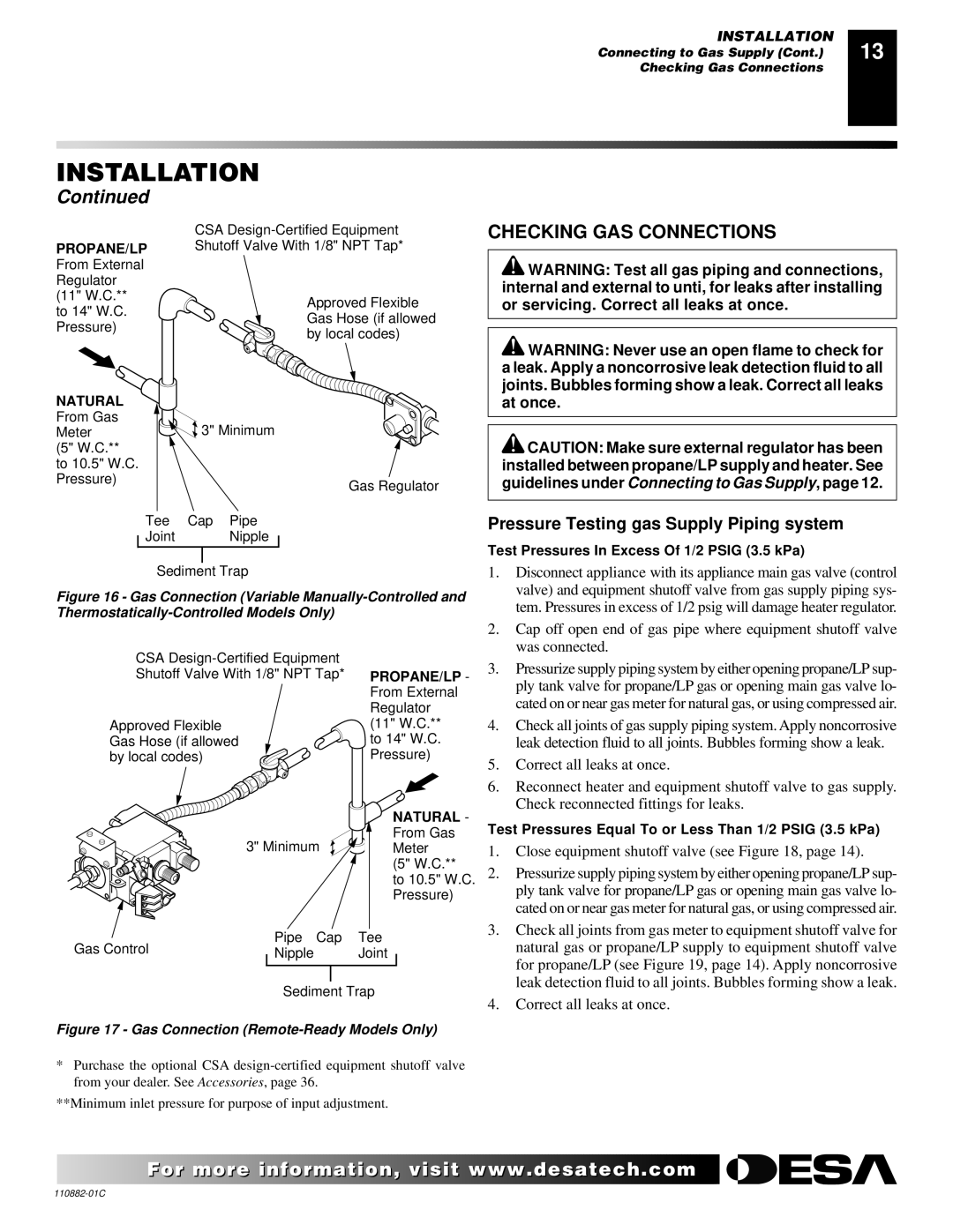
PROPANE/LP | Shutoff Valve With 1/8" NPT Tap* | |
From External |
| |
Regulator |
| |
(11" W.C.** | Approved Flexible | |
to 14" W.C. | ||
Gas Hose (if allowed | ||
Pressure) | ||
by local codes) | ||
| ||
NATURAL |
| |
From Gas | 3" Minimum | |
Meter | ||
(5" W.C.** |
| |
to 10.5" W.C. |
| |
Pressure) | Gas Regulator | |
|
Tee Cap Pipe
Joint Nipple
Sediment Trap
Figure 16 - Gas Connection (Variable Manually-Controlled and Thermostatically-Controlled Models Only)
INSTALLATION | 13 |
Connecting to Gas Supply (Cont.) | |
Checking Gas Connections |
|
|
|
CHECKING GAS CONNECTIONS
![]() WARNING: Test all gas piping and connections, internal and external to unti, for leaks after installing or servicing. Correct all leaks at once.
WARNING: Test all gas piping and connections, internal and external to unti, for leaks after installing or servicing. Correct all leaks at once.
![]() WARNING: Never use an open flame to check for a leak. Apply a noncorrosive leak detection fluid to all joints. Bubbles forming show a leak. Correct all leaks at once.
WARNING: Never use an open flame to check for a leak. Apply a noncorrosive leak detection fluid to all joints. Bubbles forming show a leak. Correct all leaks at once.
![]() CAUTION: Make sure external regulator has been installed between propane/LP supply and heater. See guidelines under Connecting to Gas Supply, page 12.
CAUTION: Make sure external regulator has been installed between propane/LP supply and heater. See guidelines under Connecting to Gas Supply, page 12.
Pressure Testing gas Supply Piping system
Test Pressures In Excess Of 1/2 PSIG (3.5 kPa)
1. | Disconnect appliance with its appliance main gas valve (control |
| valve) and equipment shutoff valve from gas supply piping sys- |
| tem. Pressures in excess of 1/2 psig will damage heater regulator. |
2. | Cap off open end of gas pipe where equipment shutoff valve |
| was connected. |
CSA
Approved Flexible Gas Hose (if allowed by local codes)
3" Minimum
PROPANE/LP - From External Regulator (11" W.C.**
to 14" W.C. Pressure)
NATURAL - From Gas Meter
(5" W.C.**
to 10.5" W.C. Pressure)
3. | Pressurize supply piping system by either opening propane/LP sup- |
| ply tank valve for propane/LP gas or opening main gas valve lo- |
| cated on or near gas meter for natural gas, or using compressed air. |
4. | Check all joints of gas supply piping system. Apply noncorrosive |
| leak detection fluid to all joints. Bubbles forming show a leak. |
5. | Correct all leaks at once. |
6. | Reconnect heater and equipment shutoff valve to gas supply. |
| Check reconnected fittings for leaks. |
Test Pressures Equal To or Less Than 1/2 PSIG (3.5 kPa)
1. | Close equipment shutoff valve (see Figure 18, page 14). |
2. | Pressurize supply piping system by either opening propane/LP sup- |
| ply tank valve for propane/LP gas or opening main gas valve lo- |
Gas Control | Pipe Cap | Tee | ||
Nipple | Joint |
| ||
|
| |||
|
|
|
|
|
|
|
|
|
|
Sediment Trap
Figure 17 - Gas Connection (Remote-Ready Models Only)
*Purchase the optional CSA
**Minimum inlet pressure for purpose of input adjustment.
| cated on or near gas meter for natural gas, or using compressed air. |
3. | Check all joints from gas meter to equipment shutoff valve for |
| natural gas or propane/LP supply to equipment shutoff valve |
| for propane/LP (see Figure 19, page 14). Apply noncorrosive |
| leak detection fluid to all joints. Bubbles forming show a leak. |
4. | Correct all leaks at once. |
For more![]()
![]()
![]()
![]() visit www.
visit www.![]()
![]()
![]() .com
.com![]()
![]()
![]()
![]()
![]()