OWNER’S MANUAL
SERVICE
PROCEDURES
Continued
Fan
IMPORTANT: Remove fan from motor shaft before removing motor from heater. The weight of the motor resting on the fan could damage the fan pitch.
1.Remove upper shell (see page 8).
2.Use 1/8" allen wrench to loosen set- screw which holds fan to motor shaft.
3.Slip fan off motor shaft.
4.Clean fan using a soft cloth moistened with kerosene or solvent.
5.Dry fan thoroughly.
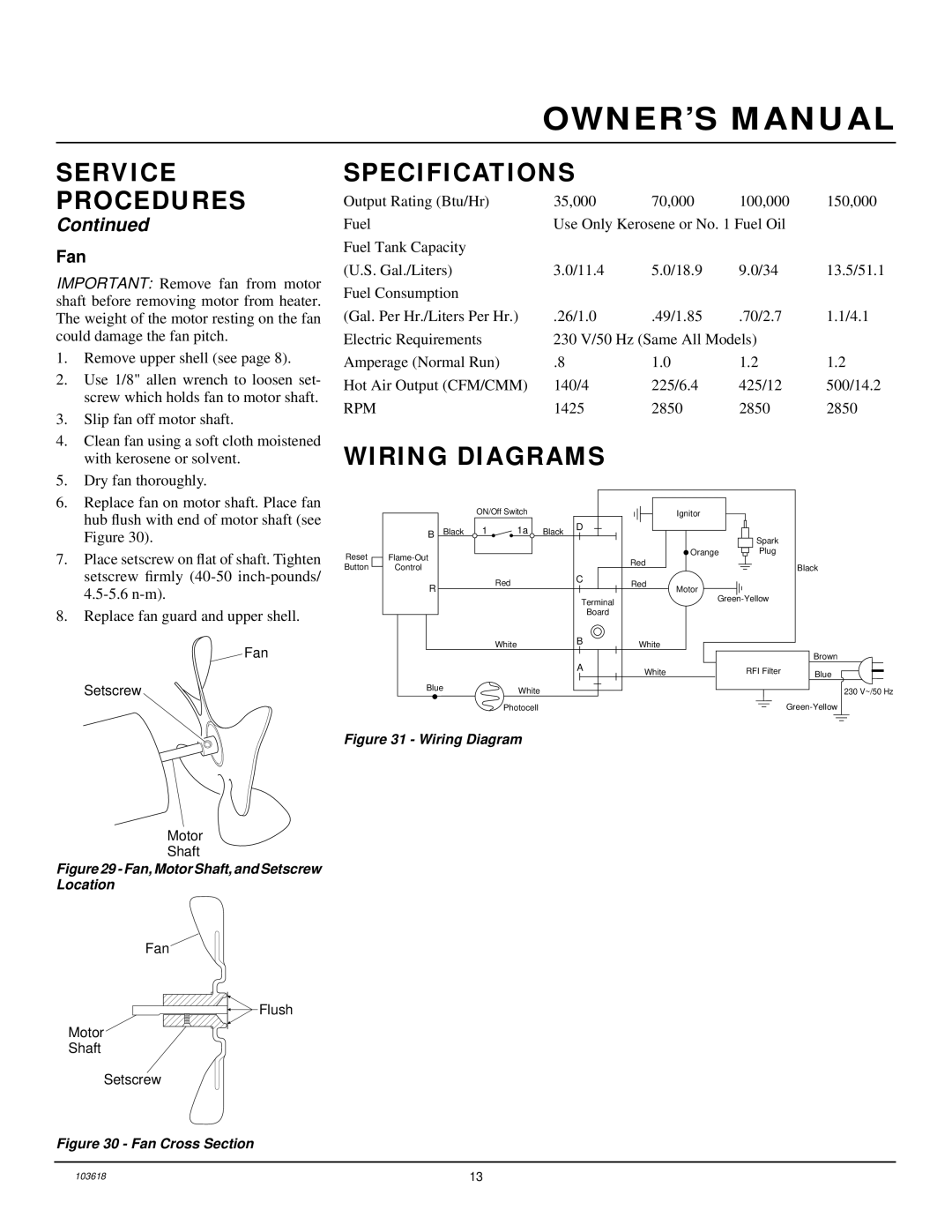
6.Replace fan on motor shaft. Place fan hub flush with end of motor shaft (see Figure 30).
7.Place setscrew on flat of shaft. Tighten setscrew firmly
8.Replace fan guard and upper shell.
Fan
Setscrew
SPECIFICATIONS
Output Rating (Btu/Hr) | 35,000 | 70,000 | 100,000 | 150,000 |
Fuel | Use Only Kerosene or No. 1 Fuel Oil |
| ||
Fuel Tank Capacity |
|
|
|
|
(U.S. Gal./Liters) | 3.0/11.4 | 5.0/18.9 | 9.0/34 | 13.5/51.1 |
Fuel Consumption |
|
|
|
|
(Gal. Per Hr./Liters Per Hr.) | .26/1.0 | .49/1.85 | .70/2.7 | 1.1/4.1 |
Electric Requirements | 230 V/50 Hz (Same All Models) |
| ||
Amperage (Normal Run) | .8 | 1.0 | 1.2 | 1.2 |
Hot Air Output (CFM/CMM) | 140/4 | 225/6.4 | 425/12 | 500/14.2 |
RPM | 1425 | 2850 | 2850 | 2850 |
WIRING DIAGRAMS
|
|
| ON/Off Switch |
|
|
| Ignitor |
|
| |
| B | Black | 1 | 1a | Black | D |
|
|
|
|
|
|
|
| Spark |
| |||||
|
|
|
|
|
|
|
|
|
| |
Reset |
|
|
|
|
|
| Orange | Plug |
| |
|
|
|
|
| Red |
|
|
| ||
Button | Control |
|
|
|
|
|
|
| Black | |
|
|
|
|
|
|
|
| |||
| R |
|
| Red |
| C | Red | Motor |
|
|
|
|
|
|
|
|
| ||||
|
|
|
|
|
|
|
|
| ||
|
|
|
|
|
| Terminal |
|
| ||
|
|
|
|
|
|
|
|
|
| |
|
|
|
|
|
| Board |
|
|
|
|
|
|
|
| White |
| B | White |
|
|
|
|
|
|
|
|
|
|
|
| ||
|
|
|
|
|
|
|
|
|
| Brown |
|
|
|
|
|
| A | White |
| RFI Filter | Blue |
|
|
|
|
|
|
|
| |||
| Blue |
| White |
|
|
|
|
| 230 V~/50 Hz | |
|
|
|
|
|
|
|
|
| ||
|
|
|
| Photocell |
|
|
|
|
| |
Figure 31 - Wiring Diagram
Motor
Shaft
Figure 29 - Fan, Motor Shaft, and Setscrew Location
Fan
![]() Flush
Flush
Motor
Shaft
Setscrew
Figure 30 - Fan Cross Section
103618 | 13 |