FOR YOUR SAFETY
•Do not store or use gasoline or any other flam- mable vapors or liguids in the vicinity of this or any other appliance.
•Due to high temperatures, the appliance should be located out of traffic and away from furniture and draperies.
•Do not place clothing or other flammable mate- rials on or near the appliance.
•NEVER leave children unattended when a fire is burning in the fireplace.
WARNING: Improper installation, adjustment, alter- ation, service, or maintenance can cause injury, prop- erty damage, or loss of life. Refer to this manual. For assistance or additional information consult a quali- fied installer or local distributor.
WARNING: This fireplace is intended for use with wood, decorative gas appliance, and
CHECK LOCAL CODES PRIOR TO INSTALLATION
INSTALLATION
INSTRUCTIONS
INTRODUCTION
Before beginning the installation of your firebox, read these instruc- tions through, completely.
These Comfort Glow components and fireboxes are safe when installed according to this Installation Manual. Unless you use Comfort Glow components which have been designed and tested for the firebox system, you may cause a fire hazard.
The DESA International warranty will be voided by, and DESA International disclaims any responsibility for the following actions:
a)Modification of the firebox, components, doors, blower fans, air inlet system and damper control.
b)Use of any component part not manufactured or approved by DESA International, in writing, in combination with a DESA International firebox system.
Refer to your Homeowners guide for warranty information.
This wood burning fireplace complies with UL127 as a Factory- Built Fireplace and is listed and tested by Underwriters Labo- ratory, Inc.
This model is not for use in mobile homes.
WARNING: Do not install a fireplace insert in this firebox unless the manufacturer’s instructions with the insert specifically state this firebox has been tested for use with the insert.
PROPER INSTALLATION is the most important step in ensuring safe and continuous operation of this firebox. Consult the local building codes as to particular requirements concerned with the installation of all factory built fireboxes. Although grounding may not be required by code it is recommended by the manufacturer.
This firebox is not intended to be used as a substitute for a furnace to heat an entire home. Use for supplementary heating only.
MINIMUM CLEARANCES TO COMBUSTIBLES
Framing and enclosures may safely make direct contact with the spacers on the top of the firebox. The firebox may sit directly on combustible flooring (see Step 4, below). The firebox opening must not be less than 24 inches from combustible materials and the chimney must be absolutely maintained. A 16 1/2 inch inside chase dimension is recommended as a minimum size. A 3/4 inch air space is required around back and sides of firebox.
Keep all combustible furnishings a considerable distance from the firebox.
WARNING: Never use gasoline,
WARNING: Do not pack required air spaces with insulation or other material.
HEIGHT: The minimum height of the chimney, measured from the base of the firebox to the flue gas outlet, is 16 feet for a straight chimney or with one elbow set. For systems with 2 elbow sets, the minimum height is 30 feet. The maximum height of any system is 60 feet. This measurement includes the firebox, chimney sections and the effective height of the termination assembly.
GENERAL
Read the Warranty and Operating guidelines supplied with this firebox. Following these simple guidelines will ensure years of trouble free and safe usage of your firebox. If the Warranty and Operating instructions are not in your firebox, write to the address listed on the front cover.
INSTALLING THE FIREBOX
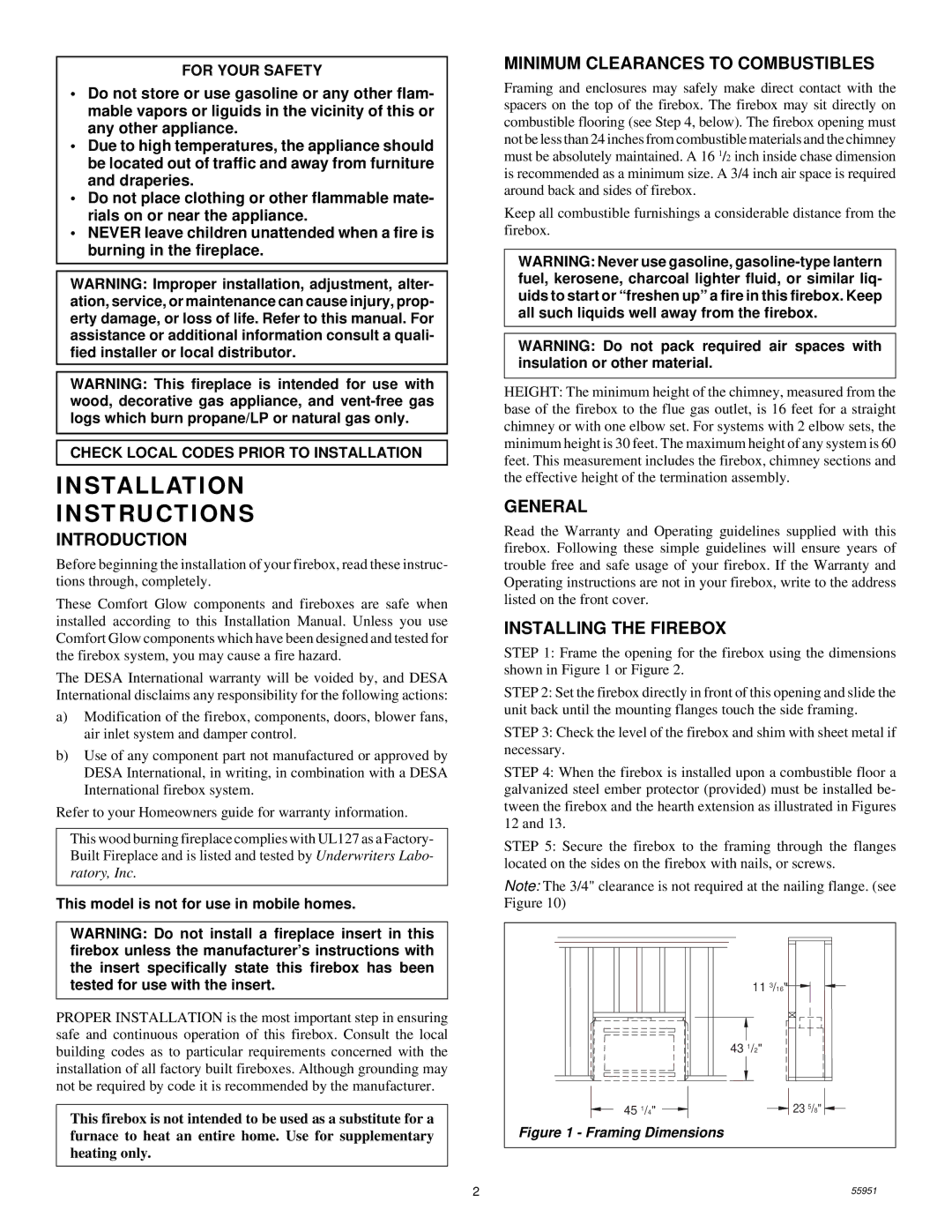
STEP 1: Frame the opening for the firebox using the dimensions shown in Figure 1 or Figure 2.
STEP 2: Set the firebox directly in front of this opening and slide the unit back until the mounting flanges touch the side framing.
STEP 3: Check the level of the firebox and shim with sheet metal if necessary.
STEP 4: When the firebox is installed upon a combustible floor a galvanized steel ember protector (provided) must be installed be- tween the firebox and the hearth extension as illustrated in Figures 12 and 13.
STEP 5: Secure the firebox to the framing through the flanges located on the sides on the firebox with nails, or screws.
Note: The 3/4" clearance is not required at the nailing flange. (see Figure 10)
| 11 3/16" |
| 43 1/2" |
45 1/4" | 23 5/8" |
Figure 1 - Framing Dimensions
2 | 55951 |
